Adding a new meter and PVD communication
Introduction
The document describes the mechanism and method of data acquisition from electricity meters. For this we use the IEC-62056 energy protocol and communication with energy meters using edge-computing devices equipped with the PVD application.
This tutorial shows the steps and how to get data from an external device to your system. Using the PVD application dedicated to Windows/Linux systems as well as embedded computing/edge computing devices, we can implement this solution for this type of device, but also for other protocols and types of devices. The mechanism will remain the same, only the configuration of the parameters of the devices and the PVD application will change.
| PVD application documentation is in the user manual section. It contains all the information necessary to run and deploy this application on supported architectures. |
Task: A new electricity meter was connected to the data acquisition system. This is the same type of meter as the existing ones and it is connected to the same bus as several other meters. Communication with the device via the RS-485 bus and the IEC-62056 energy protocol. Connect the device to the system so that the measurements of this device appear in the application and can be used in data analysis and in the operation of the AMAGE system.
Meter definition and connection design
The counter in this case is a POZYTON counter of the sEAB type. Each meter is identified by its serial number. In the photo we see this counter. The device type, exact configuration and serial number of the device are marked.
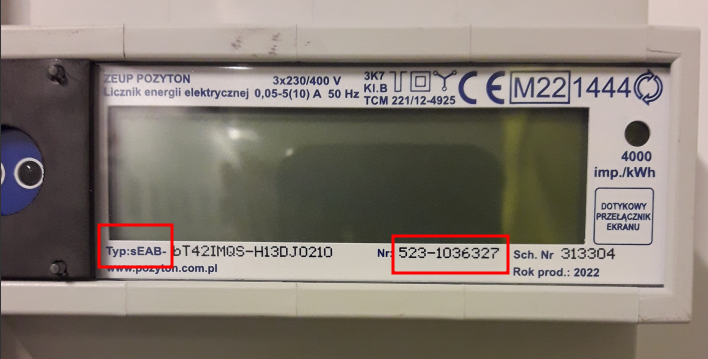
The meter has been connected to the existing measurement infrastructure. The meter was mounted on the TL-4 meter board and connected to the RS-485 bus in accordance with the diagram below.
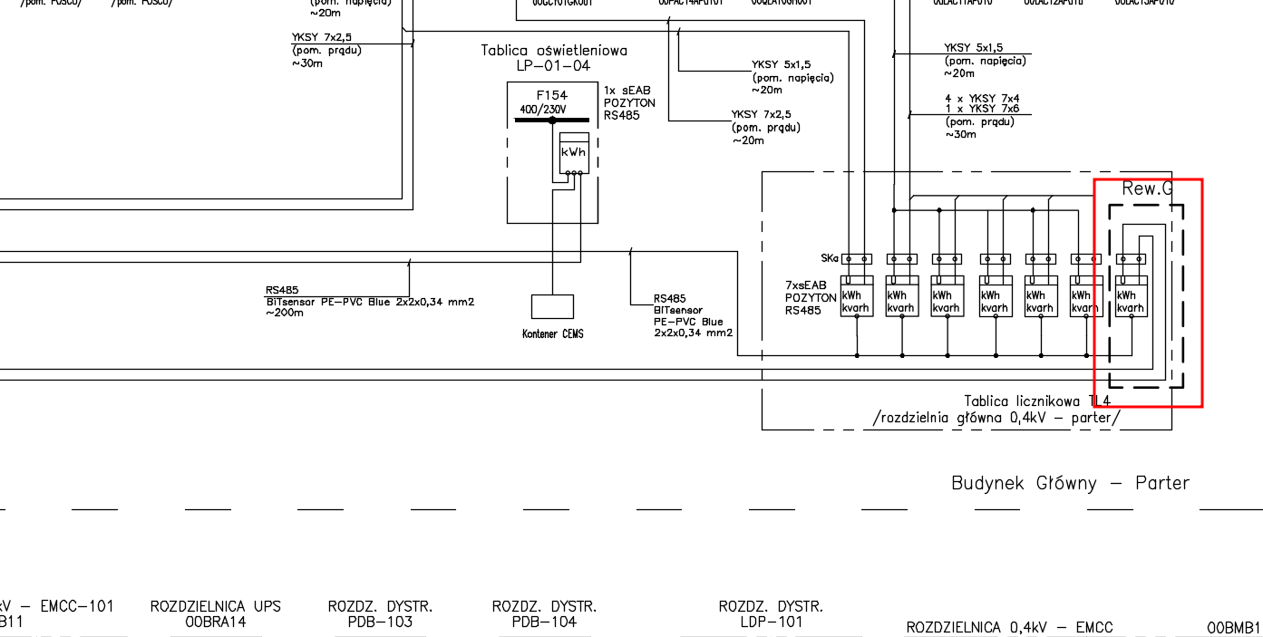
From what we can see, it has been connected next to the TL4-* meters and, according to the sequential numbering, it should receive the TL4-P7 identifier. We need to add such a counter to the system.
Adding a counter to the system
We run the AMAGE application (log in via a web browser). We go to the resource structure view. In this case, we display a list of element groups and go in this structure to a group of counters from the TL4 table. We filter the view and get a view of the current counters installed there:
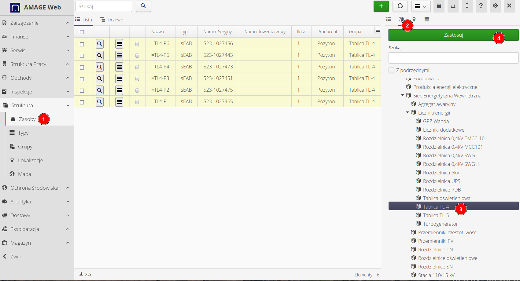
On the view, the filter dialog has been displayed and docked permanently in the view. How to do this is described in the main user manual. The filter is available in the pull-out panel with the text Filter
|
Viewing the current meter, we can see its basic parameters (serial number, type, etc.) and parameters definable for the type specific for this meter model (sEAB manufactured by POZYTON).
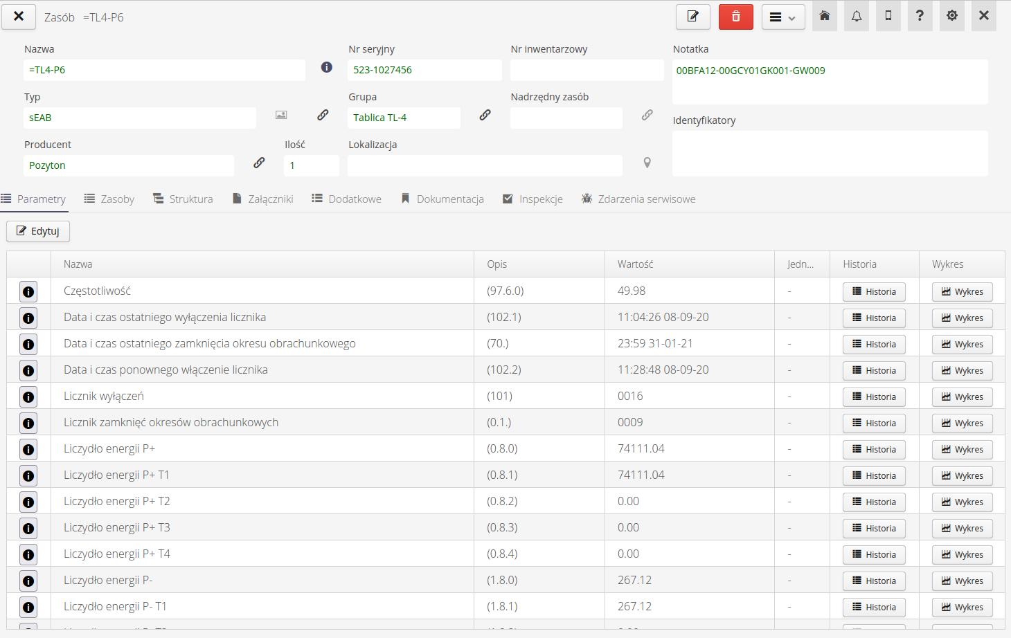
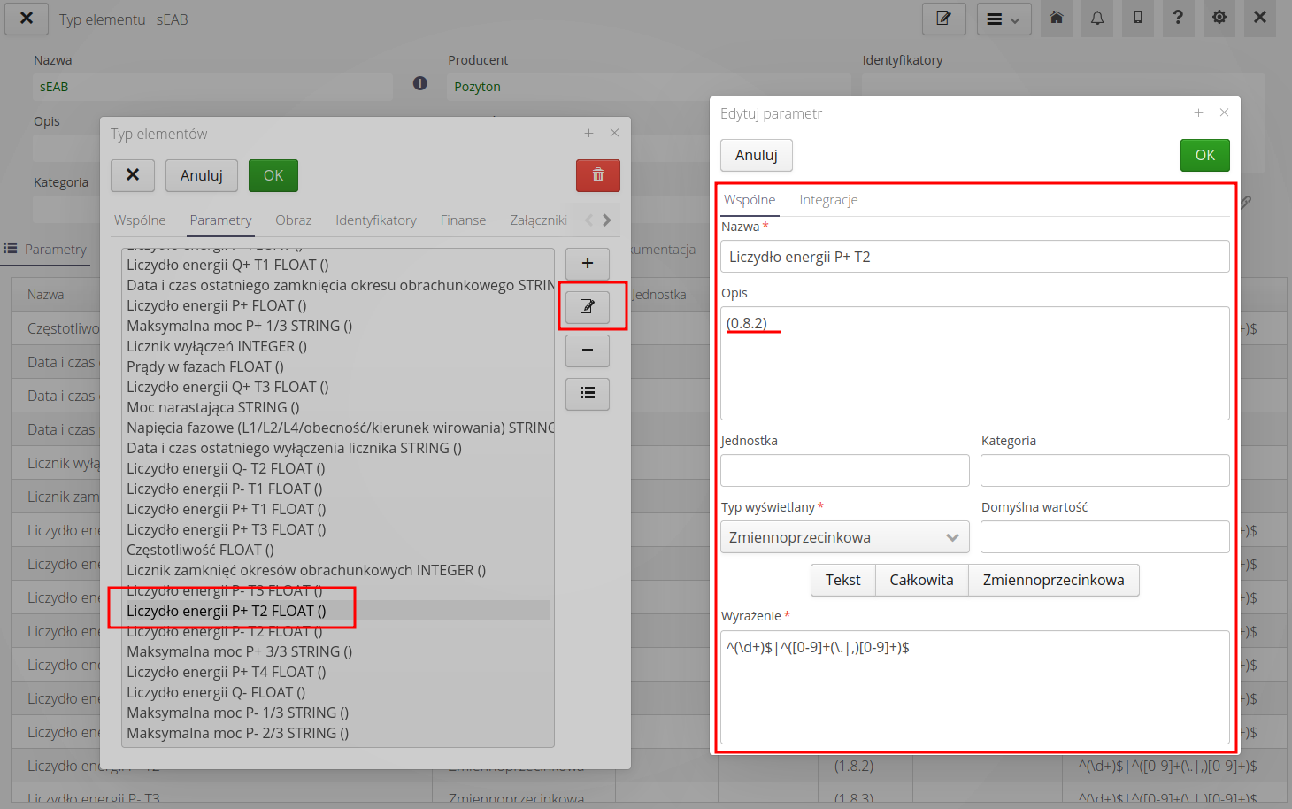
Going to the view of the type of element defining this resource, we see parameters that all resources of this type have. The view of any parameter (element type edition mode) and the properties of a given parameter are marked in the drawing. The additional information includes the parameter identifier (0.8.0) corresponding to the query code for the IEC-62056 protocol.
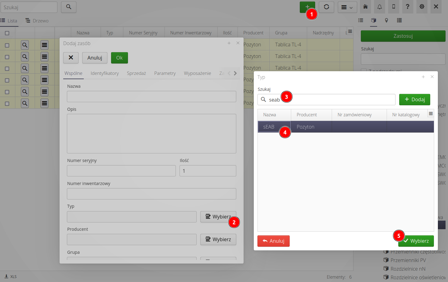
We return to the list of resources and choose to add a new resource. The appropriate group of elements (counters on TL4) will be selected automatically. Select the type of device - here type sEAB.
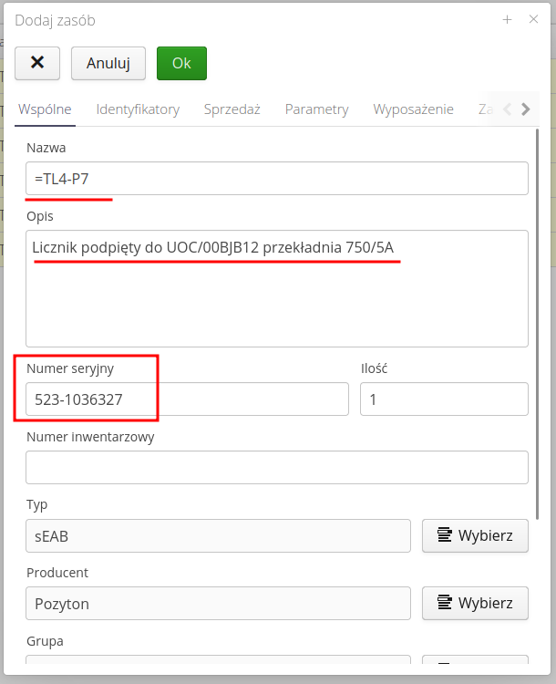
Next, we define the basic data of the counter. Its serial number etc.
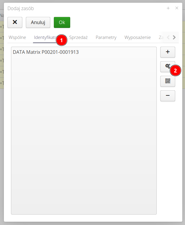
For the sake of order, we additionally generate an identifier number that can be used to print a label with a QR/Datamatrix code for quick identification by mobile devices.
| Label printing and personalization are described in a separate document/tutorial on labels and report design. |
As a result of this action, we get a new electricity meter available in the system. It has all the parameters that come from a given element type.
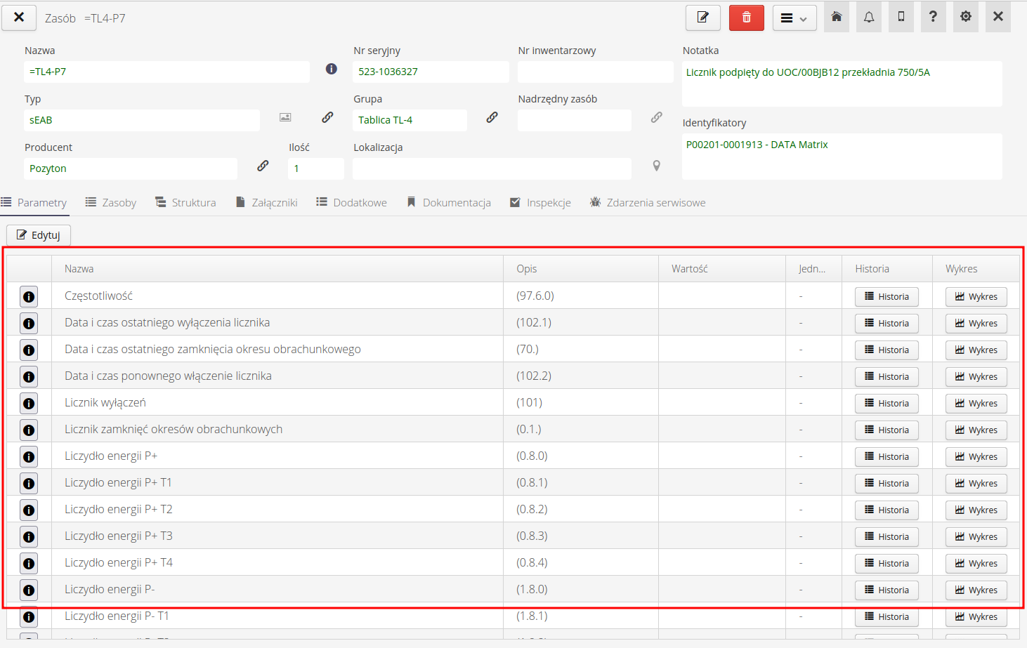
Now it remains for us to configure the PVD application so that it starts reading the parameters of this energy meter and sends them to the main system to the appropriate parameters visible in the details of the given device.
PVD communication configuration
To enable communication in the PVD application, we need information about what we will read (what device, what properties, e.g. registers) and where we will save the read values in the main system.
In the resource details view, select an action from the context menu to generate a parameter mapping in JSON format.
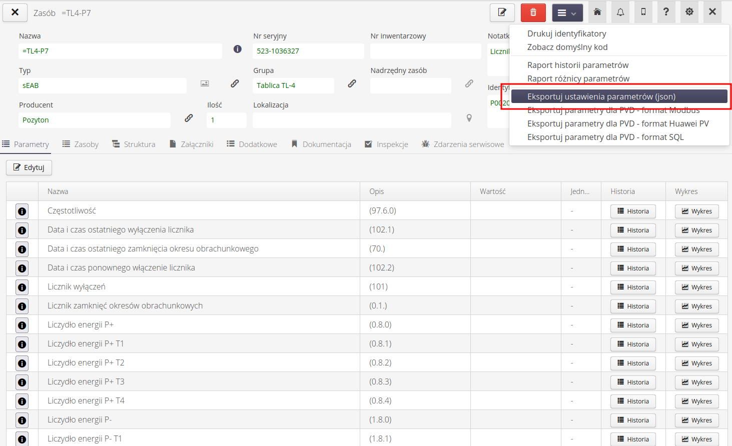
The result is a file that contains pairs - parameter name and parameter UUID code. The UUID code is a unique identifier for a given parameter. It is a globally (worldwide) unique code, which allows unambiguous determination of these values.
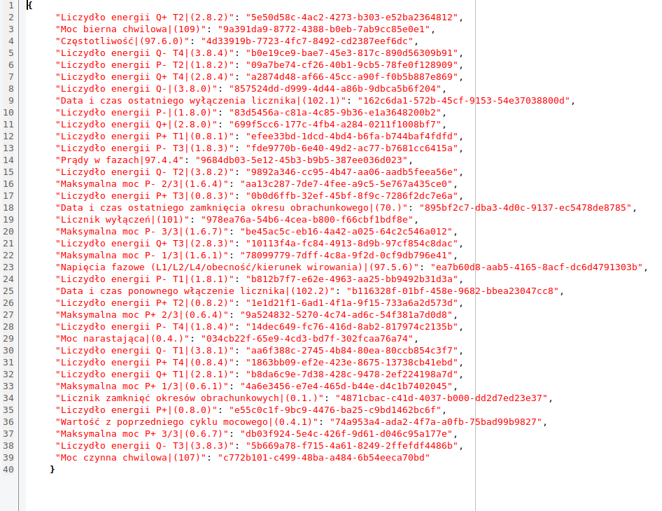
Having such a mapping, we proceed to the configuration of the PVD application. This application has a so-called IEC-62056-21 suppliers. The configuration is in JSON format and contains information about serial ports for communication with meters and meter parameters.
In this case, we already have an existing configuration. In this case, we are looking for an already existing TL4-P6 counter in the file. We can see its configuration and all data. We will use this data to copy and create a new configuration for the new meter.
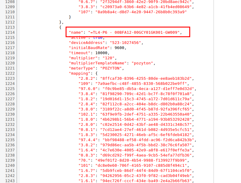
| A detailed description of the configuration with examples is available in the PVD application user manual. |
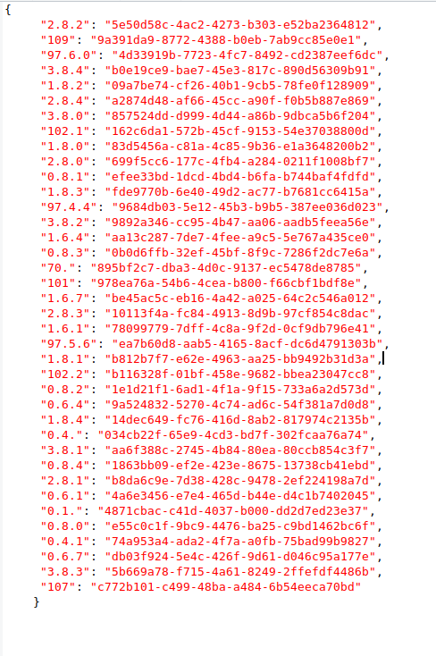
In order to use the already defined data that we downloaded from the system to a format compatible with PVD, we must get rid of the names of the parameters and leave only the parameter identifier in the first element of each pair in accordance with the IEC-62056-21 protocol.
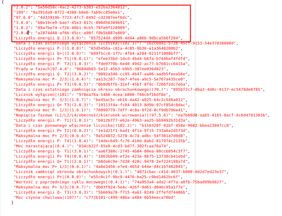
| For details of the parameters, their properties and names, refer to the documentation of the communication protocol of the selected device. |
The mapping created in this way: <IEC-62056-21 parameter> → <UUID code of the parameter in the system> is pasted into the meter mapping.
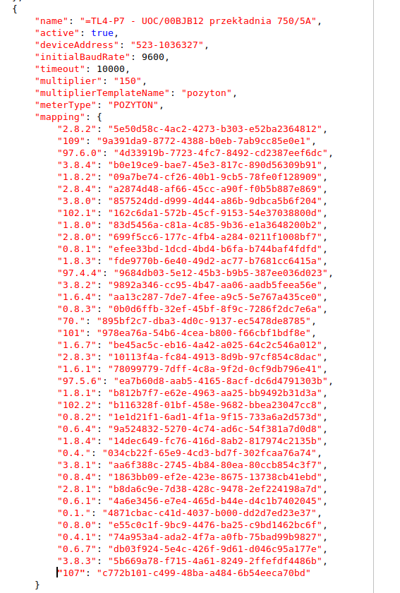
| According to the system design, a current transformer in the range of 750/5A was used for the measuring circuit. This is visible in the documentation. In order to properly scale the meter measurements to the actual results (and not those measured on the secondary side of the transformer), we must multiply the numerical parameters by 150 (750/5). |
In addition, therefore, we set the multiplier parameter to 150. The other parameters remain the same. We get the counter mapping ready:
We place such mapping after the TL4-P6 counter in the same section of the communication protocol and port (in this case COM10).
The system configuration is ready for testing and production deployment. However, in order to quickly check only a given meter, we will make a few (temporary) modifications to the meter and PVD configuration file.
Testing
To quickly test communication with a given meter, we will use a small modification of the configuration file. We do it because other meters are connected on the same bus and communication over the RS-485 bus is sequential. We would have to wait until all other meters are read. So, for testing, we turn off all other buses and counters. We do this by setting the enabled flags to false.
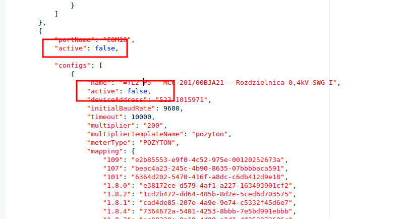
We get a ready file for testing - only one bus switched on and only one counter (our new counter).
We proceed to the tests. We disable the PVD service responsible for communication with these meters on the edge device.
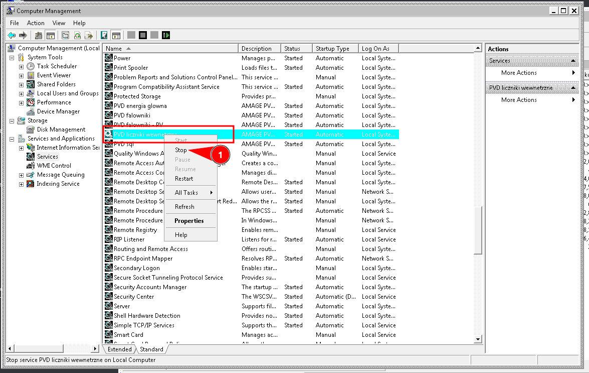
| The PVD application can be run multiple times on one edge computer and each of them can deal with one of the communication areas. |
We make a copy of the current configuration and replace it with the prepared test configuration. Please note the appropriate supplier path for your PVD instance.

Additionally, we change the 'recipient' of the data. The default was the AMAGE system and its REST interface, as seen in the core-config.json file. There we have the rest plugin enabled.
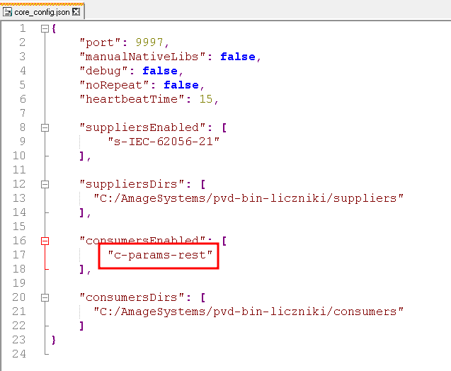
We modify this and change the recipient to the test recipient c-example. This will not send measurements to the AMAGE system in case of correct communication. Sometimes it is required to verify the measurements, see if we have defined the parameters and possible scaling correctly. The changed configuration file contains only the recipient who will save the read measurements locally in the application log.
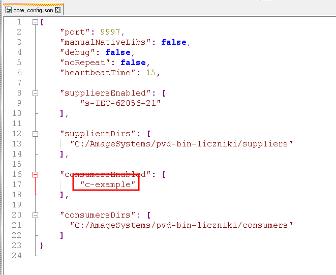
| Other 'recipients' are described in the PVD documentation. For example export to CSV format (for visualizations/charts). Please note that multiple recipients can be enabled (same as vendors). |
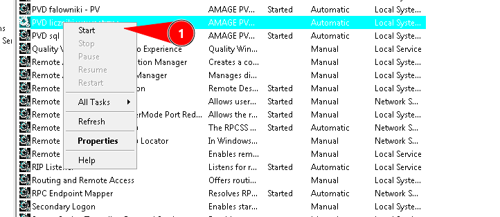
We restart the PVD instance.
We go to the PVD application log directory and verify the appropriate log file. On the screen we can see the correct reading from the meter with the given serial number and the read values.
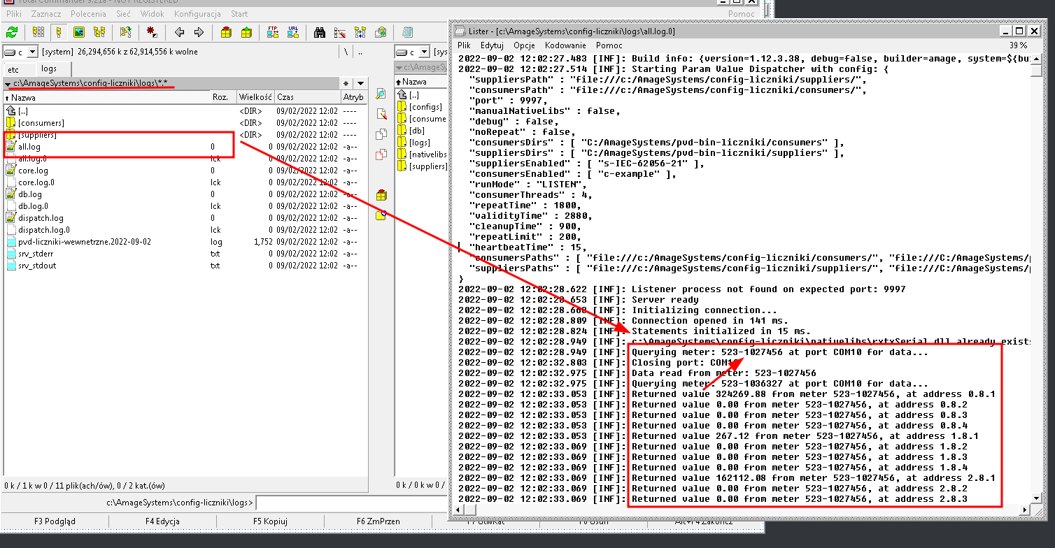
| On the last screen, the serial number (S/N) does not correspond to the initial number by definition in the AMAGE system, because this meter was not yet connected at the moment. The log shows correct communication with another meter for demonstration purposes. |
Summary
At this stage, we have configured the energy meter and entered the configuration and tests. We confirmed the correct reading of the data from the meter. The last step is to disable the PVD, replace the IEC provider configuration with the target one (with the appropriate counters enabled), change the receiver to the target REST AMAGE interface and restart the PVD. The data in the system will be updated and you will be able to view historical records in the history of the device’s parameters.
Task completed :)
| The Howto is based on system version 1.17.0.2 (03.2022) and presents features that may not be available in your system. Ask AMAGE about making this functionality available. |
| Due to ongoing development of the system, some screens or configuration files may look slightly different, but will still retain the full functionality described here. This does not affect the core functionality described in this document. |