Configuration
Configuration
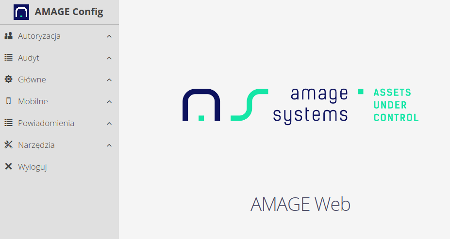
All system configuration options are available through the main menu in several sections:
-
Authorization - elements related to system access, permissions and organizational structure
-
Audit - elements of oversight of change history and access to data through network interfaces
-
Main - the main configuration elements of the system - initial data, dictionaries and others
-
Mobile - offline mobile devices and data aggregators
-
Notifications - area for managing notifications, notifications and automation of system activities
-
Integrations - data on integrations and import/export operations
-
Other sections specific to the selected system configuration
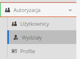
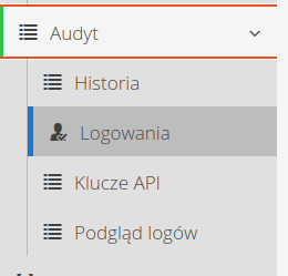
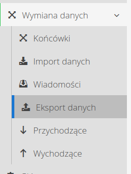
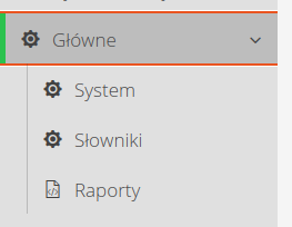
| Access to the configuration section is available only to users who have an access flag for this section (see user definition). In addition, access to individual configuration sections is defined by standard user permissions (access profiles). |
Introduction
The configuration interface is available to users who have the access flag for this interface (see user definition documentation) or are super-administrators.
When you select the option in the system menu "Configuration", the system will take you to this version of the system. In it, you can configure system functions, application automation and view other configuration data/system dictionaries.
| The premise of the application configuration section is to group system configuration areas that are used occasionally into a single interface. Normally, this part of the system should only be accessed by a selected team of people who know the users' requirements and can configure the system to their needs. |
Departments
The section of department definitions allows us to arrange employees in the organizational structure of the plant/building. With the help of this view we have the possibility to arrange the structure of employees in the tree of departments/teams.
Upon entering the departments view, we are presented with a tree view.

Context actions allow you to edit a department or add a sub-department. Adding main departments is done by pressing the main button + Add.
Using the Users button, we have access to the view of users assigned to a given department.
| The view has a Drag & Drop mechanism that allows you to move departments in the tree and between elements. |
Using search fields and detailed filters, we can limit the view to the selected tree/section of the system. In the tree view, we can also see information about the number of users who are assigned to a particular department. We can also call up a list of users assigned to a department (names of users).
Adding/editing a department involves invoking the appropriate option from the main view or entering to edit a currently existing department.
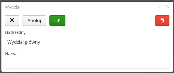
The window indicates at which level of the tree you are adding a new department (if at the main level then no information about the parent element appears) and you can enter information about the department name.
| Assignment of users to a department is implemented at the level of individual users in their view. |
Users
User management interface. Allows you to specify the permissions and identification data of employees participating in the process. The default action displays the list of users with all the basic parameters of the users.

The context menu of the main view provides actions to present additional data about the user(s).
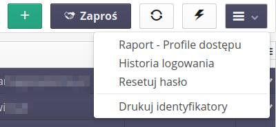
Available actions
-
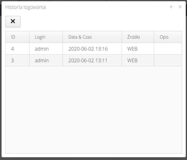
show login history - displays a window with the user’s login history and its source (Web application, Fx mobile application, etc.)
-
Access profiles report - a report with a list of access profiles for a selected user along with a list of active functions (and their IDs)
-
Reset password - password reset
-
Print IDs - print IDs for selected users
The + button allows you to add a new user. The Invite button allows you to invite new users by sending an email invitation. The refresh button resets the view and applied filters, and the lightning button displays the event and automation definition window.
The context menu in the user list allows you to perform operations on the selected user or user group.
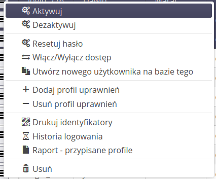
Options available:
-
Activate - user activation
-
Deactivate - deactivate user
-
Reset Password - opens a dialog box to reset the password and prints a new password or sends the activation procedure to an email address
-
Enable/disable access - change system access flag
-
Create user based on this - create a new user based on existing user data, e.g. permission profiles
-
Add/Remove Permission Profile - bulk add/remove permission profile
-
Print badges - print badges for selected users.
-
Login History - Displays the user’s login history
-
Report - assigned profiles - display a report with assigned user profiles and functions to which they have access
-
Delete - remove user
User properties
Properties are divided into sections with separate functionality:
-
General - general user data
-
Access - access to individual system sections/system flags.
-
Data - identification data
-
Identifiers - identifiers in the form of bar codes, RFID cards, etc.
-
Profile - list of access profiles to which the user is assigned.
-
Picture - a photo of the user (e.g. for control functions).
-
Signature - user signature - for use in document generators.
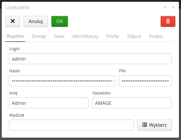
In general, information includes login dale, first name, last name and departmental classification in the organization.
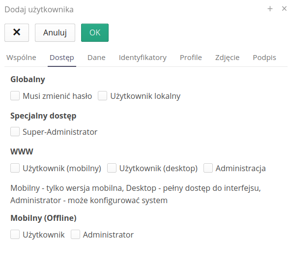
Access flags determine a user’s privileges to access dedicated application sections or various system applications. Flags:
-
Must change password - local user will be prompted to change password the next time they log in
-
Local user - the user authenticates with a password/pin stored locally on the system (as opposed to corporate users who authenticate with external systems - OAuth/Active Directory/LDAP)
-
Super-Administrator - enabling this flag skips permission checking against access profiles (the user will always have access)
-
WWW - define access to the section of the WWW application (current)
-
Mobile user - only access to the mobile part of the interface
-
Desktop user - access to the main part of the system for computers
-
Administration - access to the system configuration section
-
-
Mobile (Offline) - defining access to the mobile application enabling offline work
| User activation/deactivation is performed in the user list view using dedicated buttons. |
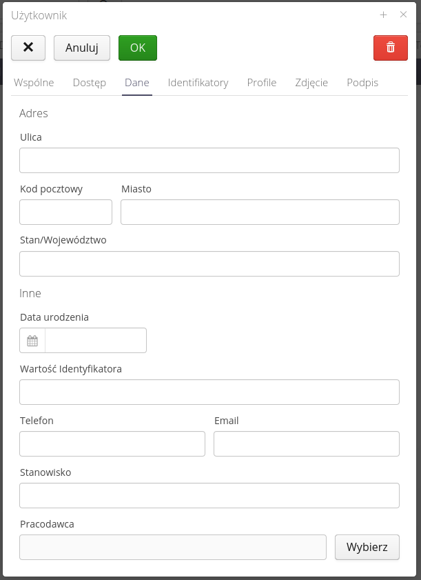
The user’s data regarding his contact address, email address, the employer with whom he is employed.
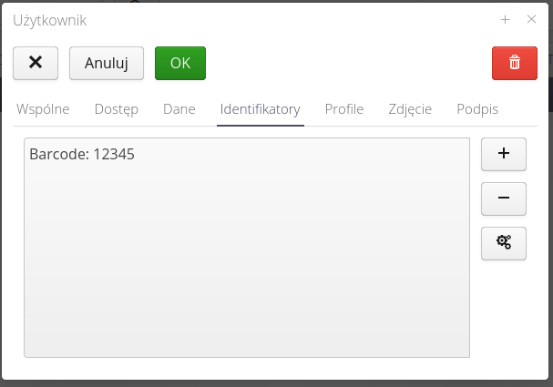
A list of identifiers in the form of 2D, RFID codes used to identify a particular user. Used in attendance checking modules or others requiring user identification. They can also be used for offline login to mobile applications.
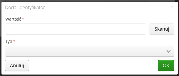
Adding an ID requires information about its value, type. You can use the RFID/barcode scanning capability of the AMAGE Shell application in this window.
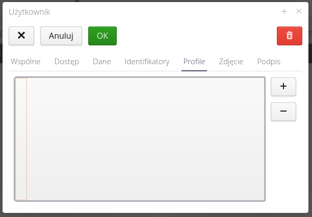
Access profiles allow you to specify a list of profiles that a user has. Profiles are added from the list.
| Access profiles add up (they are additive), i.e. a user’s permissions are the sum of the permissions resulting from the access profiles. By default, a user (ignoring the Super-Administrator flag) does not have access to any area in the system. Through access profiles, he gets access to particular areas and actions (add/delete, etc.). |
Ability to upload a photo for the user. It will be used in modules where, for example, employee verification is required. On the mobile application after reading the employee’s ID, his photo will appear.
Signature allows you to upload a scan of your signature into the system. It will be used (with the consent of the employee in question) during the execution of inspection procedures, verification or verification of deliveries - where a signature is required. In such a case (if the user has given his consent) his signature will be used in the generation of documents instead of the one entered manually.
User activation/deactivation
In addition to all the options for defining access, permissions and system sections, a user in the system has an active access flag to the system. This is the basic data checked at the beginning of the login process. If the user is inactive, he WILL NOT BE ABLE to log in to the system regardless of other permissions.
We change the user activity flag either through dedicated buttons available in the user list or through the context menu.
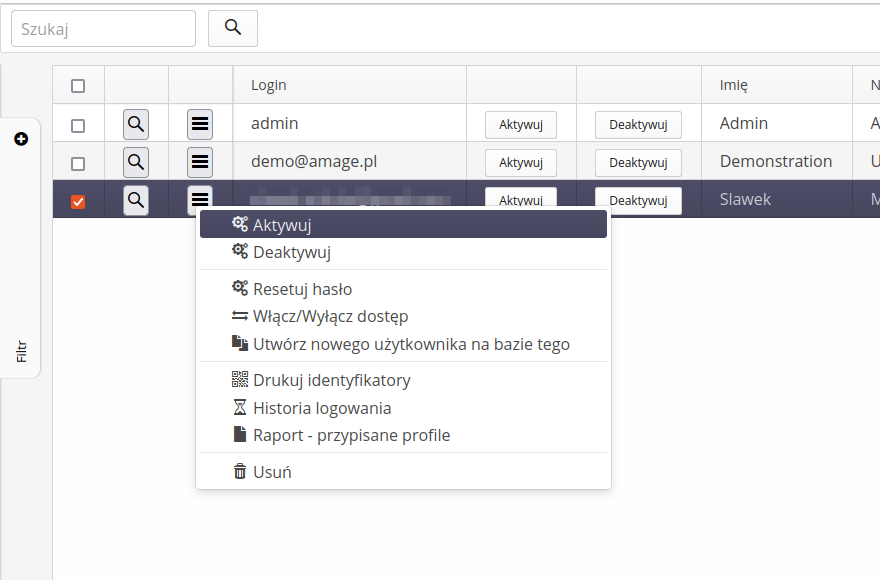
| By default, the user created has the access flag ACTIVE |
Email/print invitations
Using the 'Invite' button, you can send email invitations to join the system. The system will automatically create users and send an invitation to them to activate their accounts and set their passwords.
| In this way, we only create local users, i.e. those who authorize themselves with a local password. We will not add users to external authorization systems in this way. |
After activating the action, a window is displayed in which we can enter a list of email addresses (each in a new line) to which the invitation will be sent.
Next, we can specify how to create user logins. It can be a login that is only the name of a given email address or the whole email address. We choose this using the option available there.
We also have the ability to modify/extend the invitation to the system. Of course, texts with links to log in and reset your password will be added to the text of the invitation.
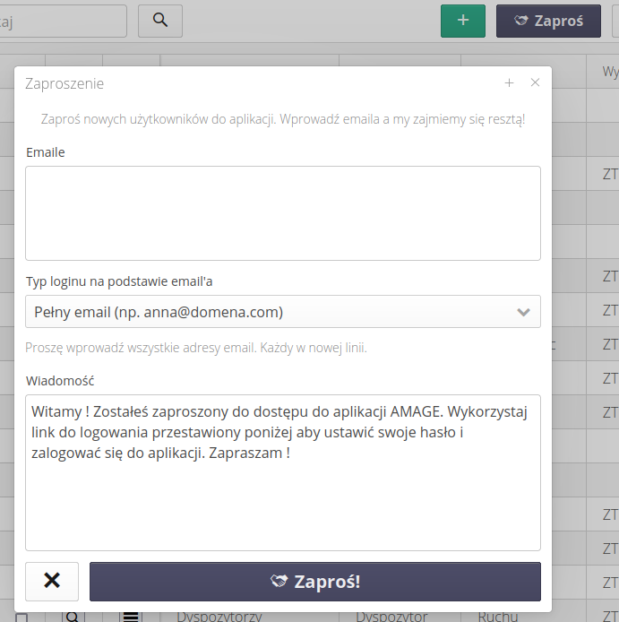
| Only a user with system administrator rights can send an invitation. This allows you to control the users you create. |
If an invitation for external users is created by a person with system administrator rights, you can indicate in the invitation form which rights the user should have. If the invitation is created by a person with user rights, it is not possible to indicate the user’s rights in the invitation form. We select permissions from available access profiles.
What’s more, if a user has super-administrator privileges, the flag for granting the same privileges to invited users is activated.
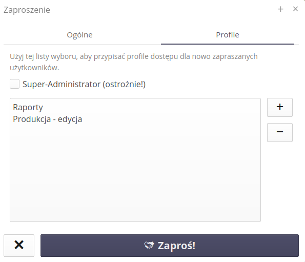
For users who have the right to edit users, an additional tab appears when inviting them, allowing them to define access profiles for users. If the user is a super-administrator, he can also give this flag to newly invited users.
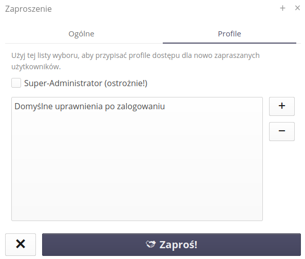
| The access mechanism should be approached with understanding and knowledge of the assigned permissions. Otherwise, new users will receive access beyond their default permissions. |
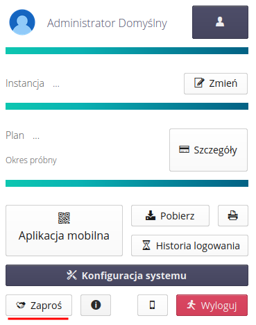
We can also invite users from the system menu, which has a built-in Invite action at the bottom, which will open the same window as the action from the configuration section.
Access profiles
Access profiles provide a central point for granting authorizations to various sections and functions of the system. Each user who is logged into the system is subject to a check of his/her privileges by the profile system. If a user is not granted access to a given group of rights then:
-
Individual areas are not displayed to him - if he does not have access to the "List Deliveries" function, he will not be presented with a link in the main menu regarding access to the Deliveries section.
-
Actions within a section of the system are not possible to run. The functions appear i.e. if the user has access to the Deliveries section, he will be able to view the delivery documents. Actions will appear to him in the context menu, buttons will be active. On the other hand, if he does not have the authorization, for example, to add a new delivery, after selecting the (+) button, he will receive a message about the lack of authorization to perform such an action.
| The above does not apply to users who have the "Super-Administrator" flag enabled. By design, such a flag bypasses checking access profiles. This allows seamless access to the full system interface, e.g. to determine access rights for other users. This user flag should not be abused. |
When you enter the access profiles section, a list of profiles and information about the number of functions defined in the profile is displayed.
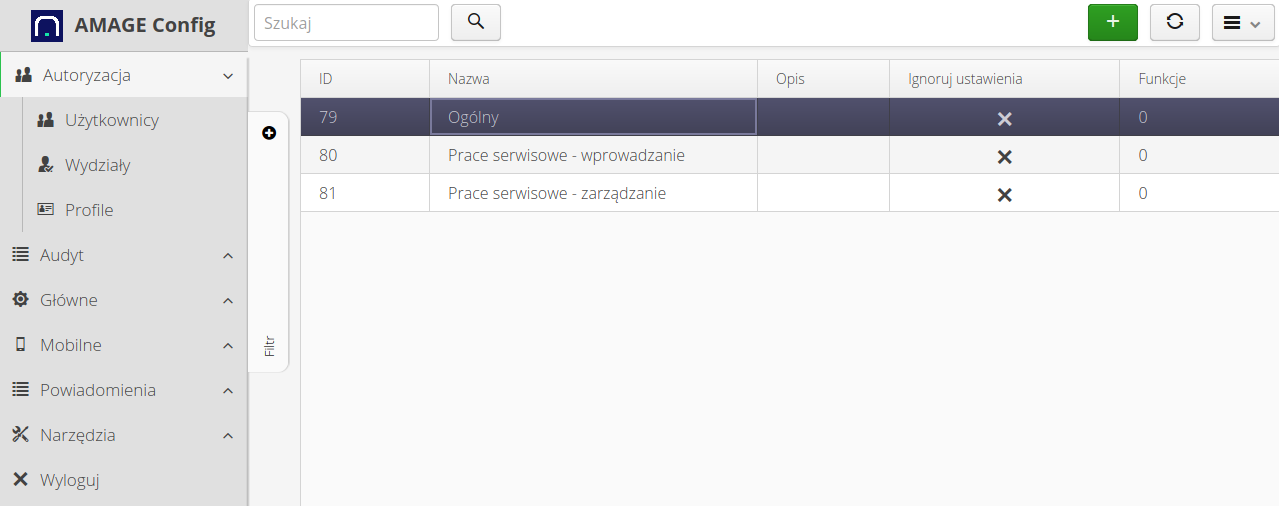
Editing/adding a profile allows you to specify the list of functions that are allowed in the profile.
The profile list context menu allows you to access selected functions for all access profiles.
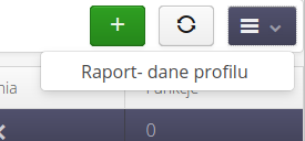
-
Report - profile data - allows you to generate a summary report with a list of permissions granted to each access profile (list of functions that the profile has active)
Access profiles add up to each other, i.e., the functions that are specified in different access profiles are summed up. Each user can have multiple assigned access profiles and is permissions will be the SUM of the permissions from the different access profiles. This allows you to define access profiles by specifying a set of activities, e.g. "Service events - overview", "Service events - create and edit" and then assign such access profiles to selected users. This allows you to easily define a set of permissions for users and modify them flexibly.
Adding an access profile displays an editing window. In the common data we specify the name and description of the profile.
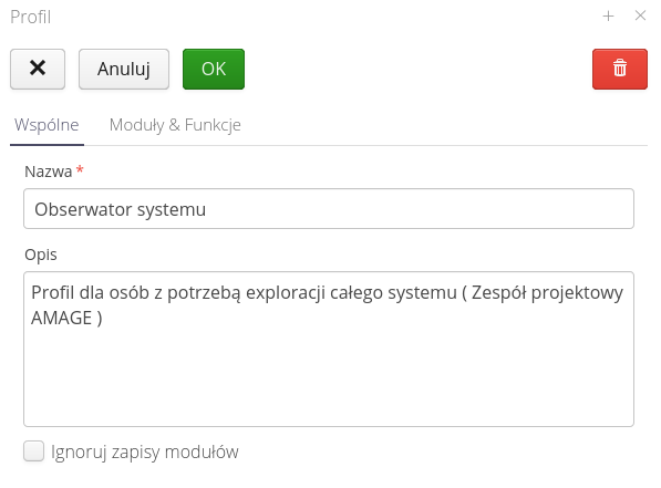
In the Modules and functions tab, we specify the list of permissions by module. To specify a function of your choice, select a module and then use the whiskers to specify which functions the access profile allows.
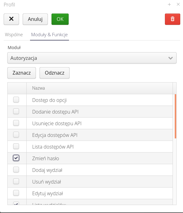
The functions are divided into modules. Only active modules in the system are visible to the defining access profile. The lists are usually divided into operations: viewing data, creating a new record, editing an existing record and deleting a record. In addition, module-specific functions appear, for which it was decided to separate permissions so that access to the execution of these functions can be better controlled.
| In order to check the permissions defined in a given profile, the easiest way to test is to use a created test user who has a given profile assigned and an additional browser session in the so-called incognito mode. In this way we can use one browser to log in simultaneously as two different users. |
Events and reactions
An interface for the definition of events that result from changes in data in the system. The mechanism allows for flexible generation of email notifications/notifications in the system with full control over the handling of these events.
The event mechanism allows you to configure responses to occurring events in the system. The event mechanism operates at the Objects level. The system operator has the ability to define events for basic operations performed on objects: Creation, Modification, Deletion. Based on these basic operations, he can further configure whether the system will respond to a given event by modifying check scripts. They allow to introduce additional conditions based on the data of a specific object, e.g. state. With the help of modifying scripts, the user can change the parameters of the event based on the data coming from the object, e.g. filling the list of email recipients based on the parameters of the object, e.g. the person assigned to the service event.
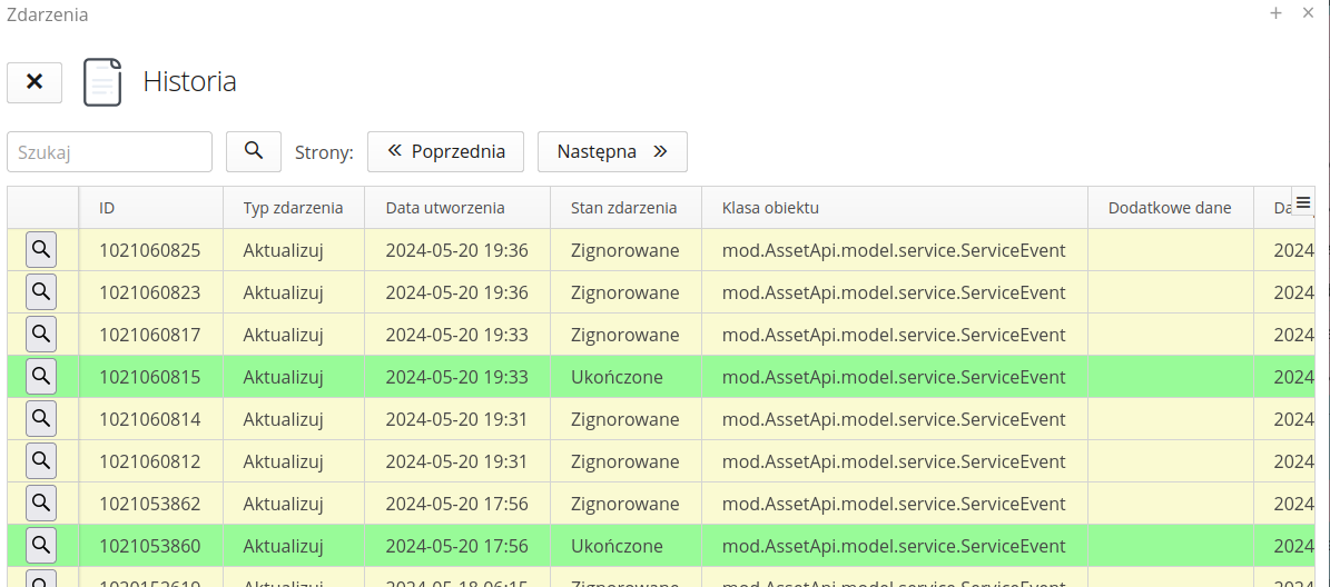
The event list allows you to view completed event handling in the system. If an event is defined for an object, all operations on this object will be analyzed by the system. Based on the event configuration, the system will handle the event (e.g., send an email) or determine that the event is ignored (e.g., does not meet the conditions of the check script).
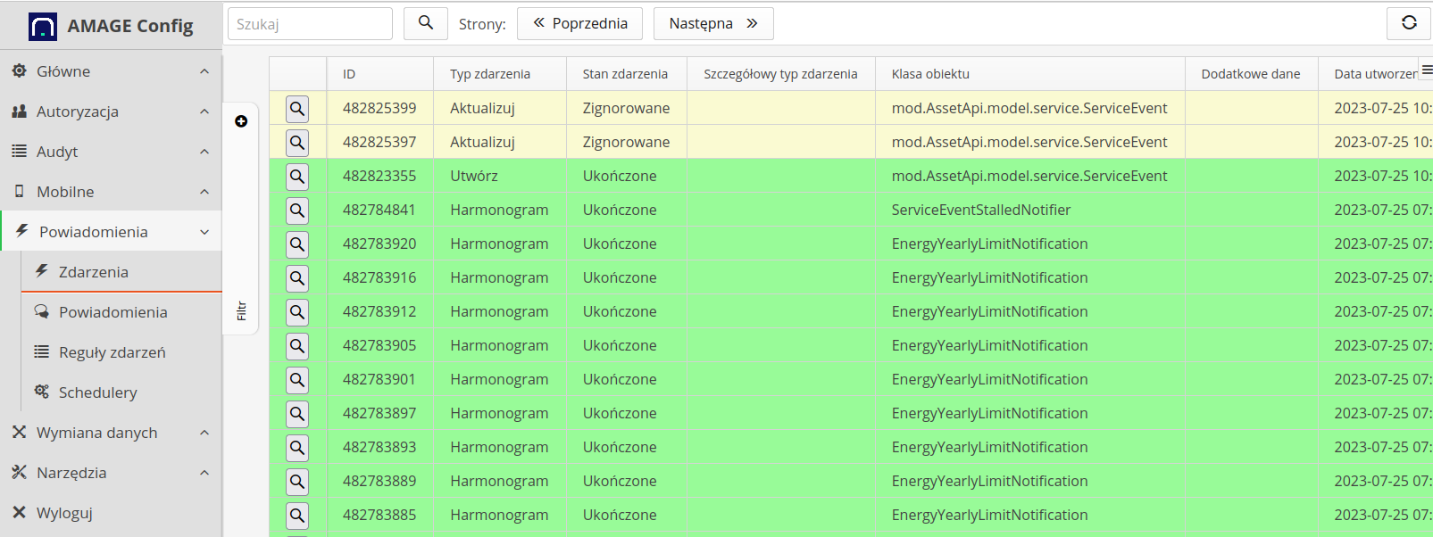
The event list shows all events and the system’s response to them. The filter allows you to selectively display the data. To see details of event processing, select any event. The system will present the details of the event.
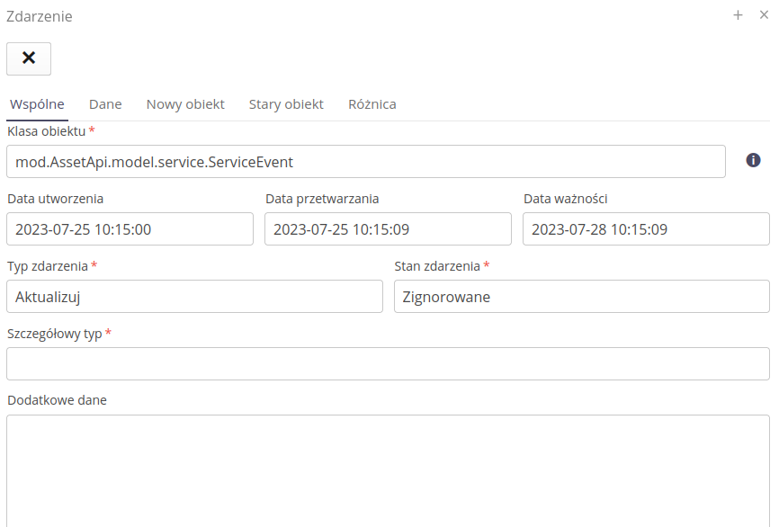
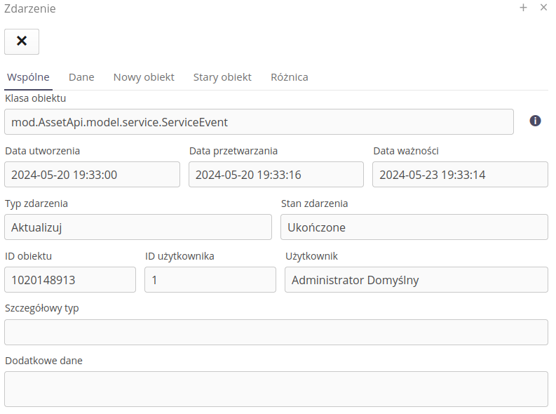
The event details show information about the event, the date it was created, processed by the system and the expiration date.
| The expiration date determines the length of time for which the system will process an event, e.g., the event of sending a message via email when the email server is not available. In this case, the system will repeat the execution of this event until the expiration time. After this time, the event will be specified as not executed. |
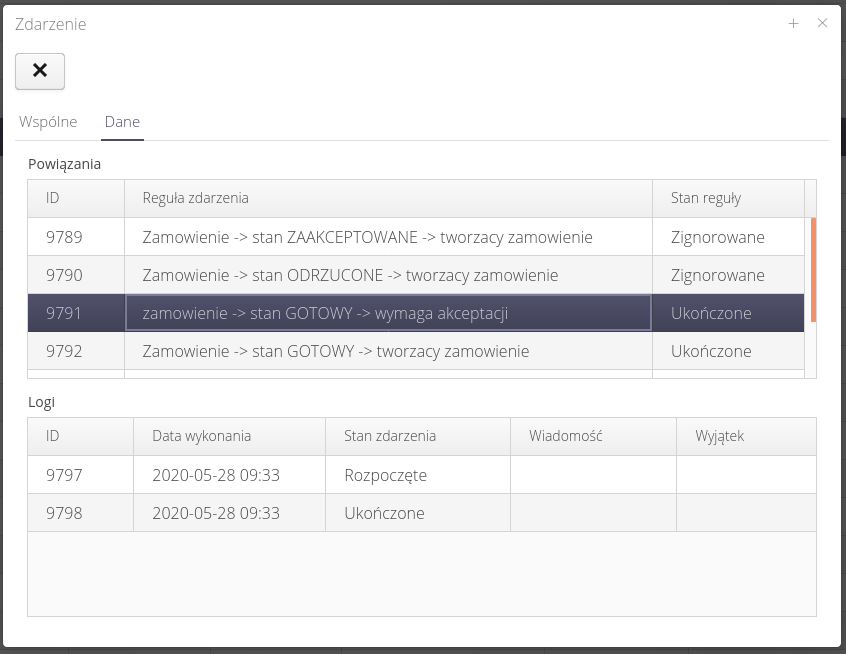
When the 'Data' tab is selected, individual system responses to an event are displayed. When an individual action is selected, the logs in the lower part of the window are presented, e.g. information about the email dispatch.
Using the views of the new/old object, we can view the structure of the saved objects. Data is shown in JSON format.
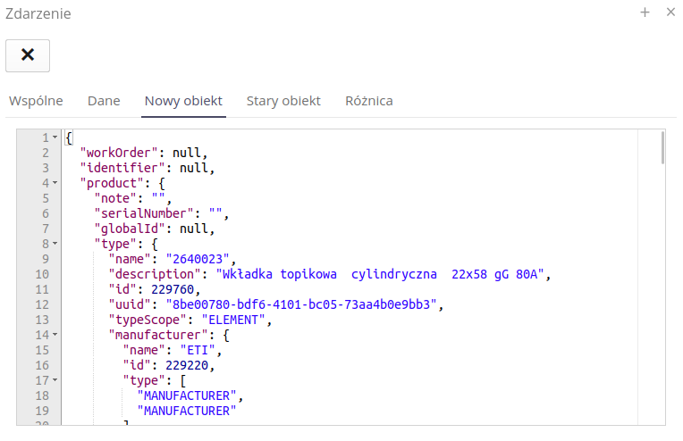
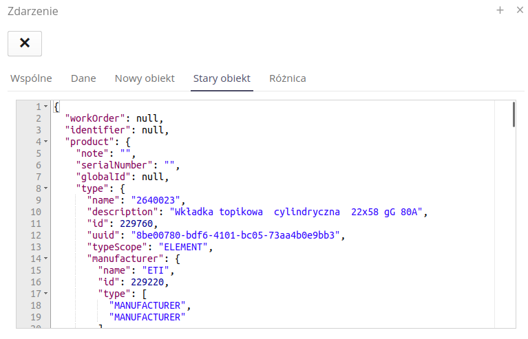
The Difference view shows the differences between the old and new records.
| This data can be used when creating event rules. Records allow access to this data presented here as JSON data. This can be used in checking scripts (e.g. checking the name of the service event status) or in notification templates (email title/content). |
Event rules
To define the system’s response to events, select the 'Event Rules' section. After selecting it, a list of event rules that have been defined in the system is presented. Adding a new rule is done by selecting (+) button.
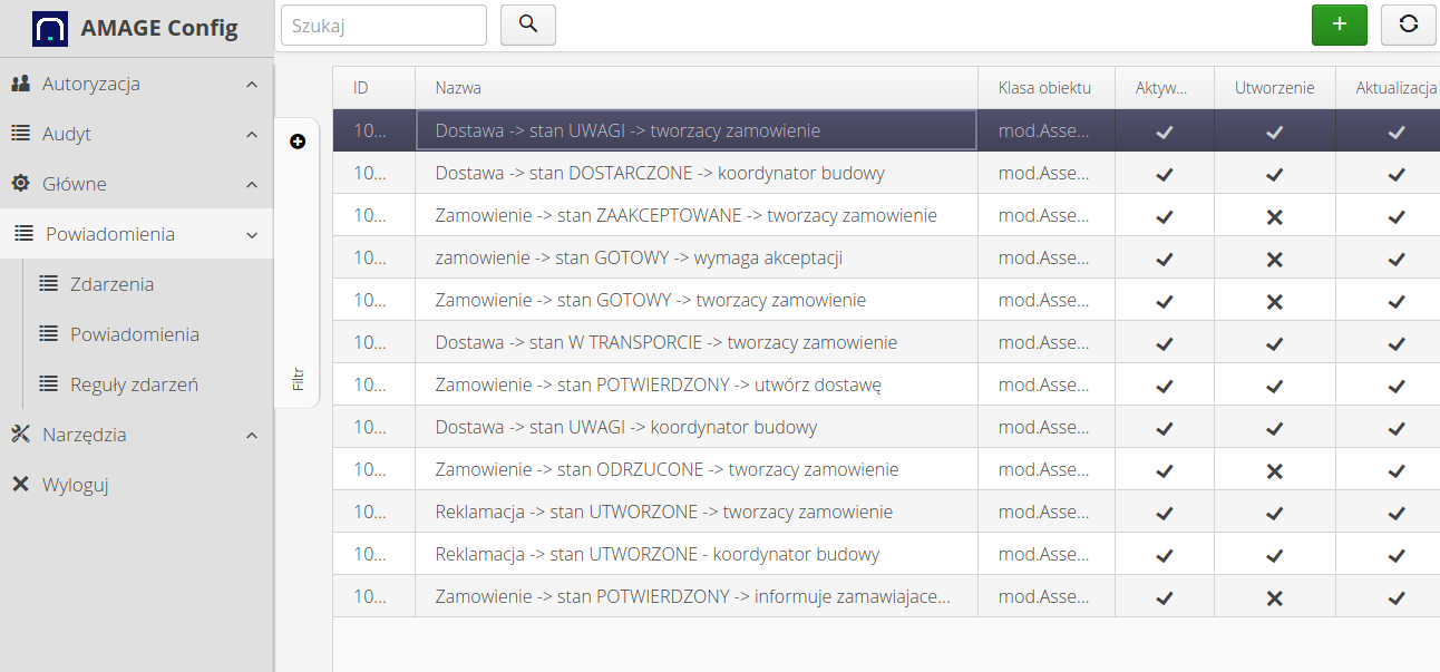
The event rule definition (or edit) is divided into several sections. The general definition of the event, the preparation script editor and the check script editor.
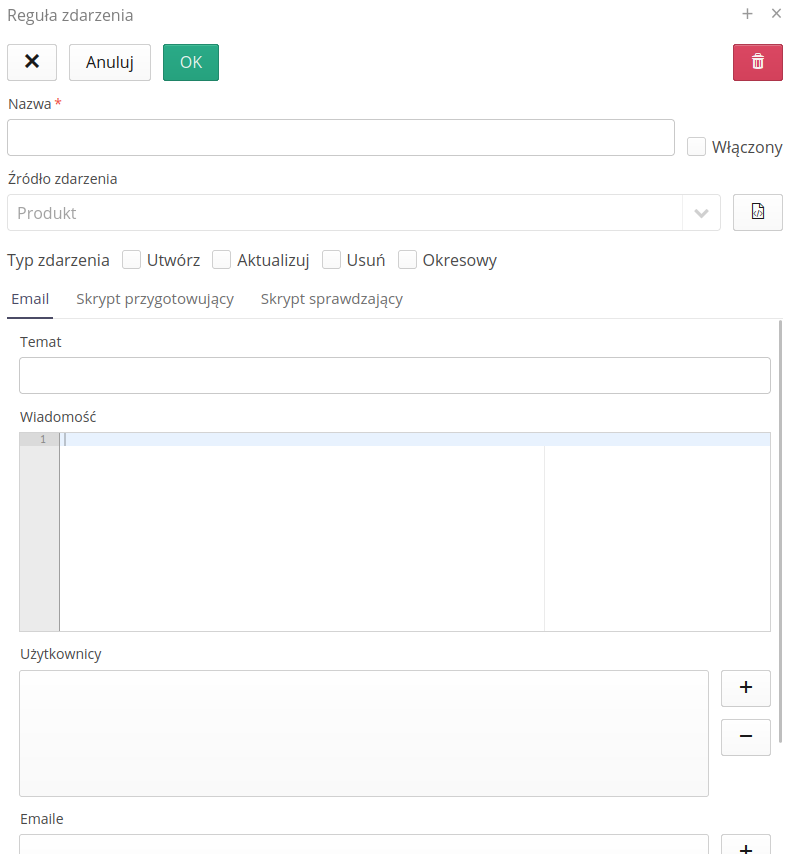
In the definition of an event rule, we specify the name visible to the system operator, the type of object affected by the event (which object will be processed by the rule). The event type determines the system’s reaction to the event, i.e. whether the action is to be performed when the object is created, changed or deleted. The 'Periodic' option refers to special periodic event responses used by schedulers.
| In the text fields of the editor, you can use a special Markdown mechanism for formatting. With its help you can generate clickable links, bold, lists, etc. Search Markdown documentation on the Web to learn about its capabilities. |
Basic data (the 'Email' tab) allows you to enter information about the basic elements of an email message, such as the title, content, and fixed fields of email addresses (from a list of users or a fixed list of any addresses).
Text fields can also use data from objects that are processed. The notation with double parentheses {{}} field_name_object is used for this. To learn about allowed fields, use the documentation in the documentation portal on the Available Events and System Configuration sections.
|
| Email addresses can be modified by the preparation script so they do not always have to be entered. Fixed email addresses can apply to notifications that are always sent to a fixed list of recipients. |
The check script allows additional filtering of events not only based on their type (create, edit, delete). The editor allows you to enter JavaScript notation, which can decide whether the script should be executed or not, based on the properties of the object fields. Detailed available fields are described in the documentation available on the documentation portal. Using these rules, we can, for example, make the execution of a script dependent on a specific state of a service event, e.g. send an email only if the event is resolved.
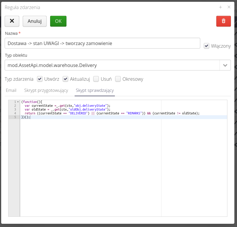
| The check function should evaluate to true/false. If the check value is true, the event will be executed. |
The preparation script allows additional modification of message fields. It can be used, for example, to update the list of email addresses based on the data of a specific object. E.g., we can send an email to the person who reported a particular service event, or send an email to the person who created an order if the order was accepted (defined in the check script).
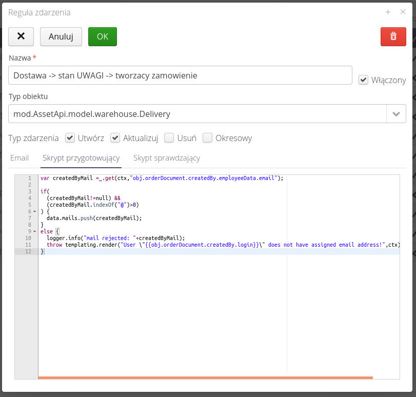
| Refer to the detailed documentation on the documentation portal to learn about all editor capabilities and available object fields. |
Event Templates
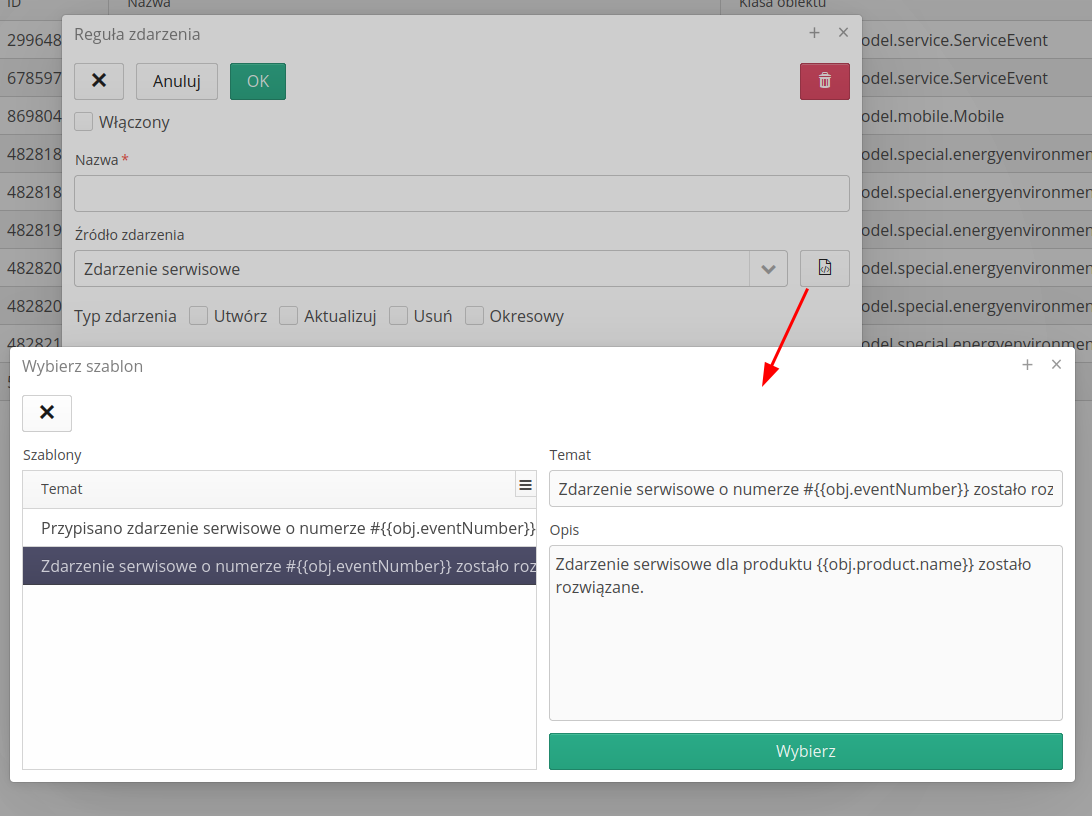
The application contains an archive of event templates that are available to the user. Event templates allow you to quickly and easily add event rules to the system. Templates contain ready-made event rules that can be customized to your needs. After selecting the button in the event editor, you go to the list of templates. After selecting the Select button, the given template is entered into the editor fields.
Automation for individual modules
The event view in the configuration section allows you to view all events defined in the system by all users. However, a view has been made available for each module, which allows you to configure events and schedules for a given functional module. This is done by a dedicated lightning bolt button, which is available in the main module views.

Using it, we can access the configuration of events and schedules for a particular module. For the 'Events' module, all events defined in the system are available. For other modules, only the events defined for the module are available.
| In order for a user to access the configuration of individual elements (schedule or events), he or she must have the appropriate permissions. If there are no permissions, only the item that is available to the user will be visible after entering the view. Of course, the user must also have permissions to access a particular functional module. |
After selecting an automation action, a window is displayed that allows you to configure individual automation elements.
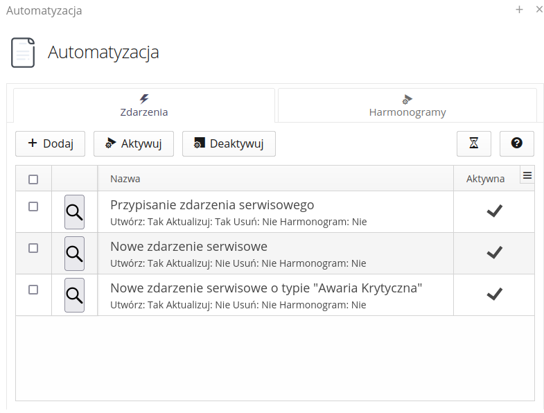
In the events view, we can add new events and edit already defined events. The available actions in the event view are:
-
Add - adding a new event
-
Activate - event activation, only the active event will be processed by the system
-
Deactivate - deactivation of the event, the event will not be processed by the system
-
History - preview of the history of events from a given module. It allows you to view the data and available event parameters
-
Help - access to help regarding the configuration of events of a specific module
Preview and Edit
Editing or creating a new event displays the event configuration window. In the event configuration window, we can define basic event parameters, such as name, event type, periodicity, and checking and preparation scripts. In this view, it is not possible to change the object that the event concerns. The object is defined at the functional module level.
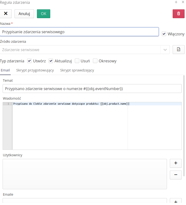
There is an additional button available in the view, located next to the object name, which displays an additional window with event templates provided by AMAGE. Templates allow you to select and enter rules into the proofreading and preparation script editors. This makes using the module and events much easier for the first time.
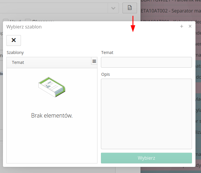
Once an event is saved, if it is active, the events are automatically activated and the system responds to new event registrations.
Operation logging and preview
To enable a full view of the events that are logged in the system, an operation logging view is available. The event history shows all events registered in the system. Information about the event, creation date, processing date and expiration date is available. The event status determines whether the event has been ignored, i.e. there are no rules for it, whether it has been executed and its final status.
The event details provide information about the event, creation date, processing date and expiration date. The 'Data' tab provides information about the old and new objects, the difference between them and data in JSON format. Using this data, we can view available fields in records and use them appropriately in scripts.
Detailed information about the operation of machines and events is available in the logs. Using the log viewer, we can view machine operations and progress in event processing.
Detailed log preview allows you to view event logs that have been recorded in the system.

Schedulers
Schedulers are the section of the system responsible for defining automatic actions that perform activities without the presence of the user. Examples of such activities are, for example, automatic generation of reports, transfer of information between users along with operations on the system, automatic generation of inspections on the basis of performed supervision activities, etc.
Each such scheduler has its own configuration capabilities. Each of them can also be run repeatedly with different parameters and with any recurrence period.
To see a list of all defined schedulers on the system and control their operation, select the Schedulers configuration section. The initial view shows a list of all defined schedulers.

The list contains information about all schedulers that are created. To create a new scheduler, select the (+) button. Editing of the selected scheduler is realized by the dedicated scheduler edit button. The Restart button causes the scheduler coordinator to reload all configurations.
| Whenever you change the configuration of the schedulers, you should select the Restart button after completing all the steps. This will let you pass the information to the scheduler coordinator, which runs all the time in the background, to read the configuration of the various elements anew. |
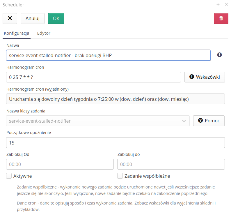
Scheduler definition/editing consists in opening the editor window. It allows you to specify the most important information about this slot machine. It is divided into two sections. The first of them defines the basic parameters of the machine. The second is a configuration specific to the selected machine.
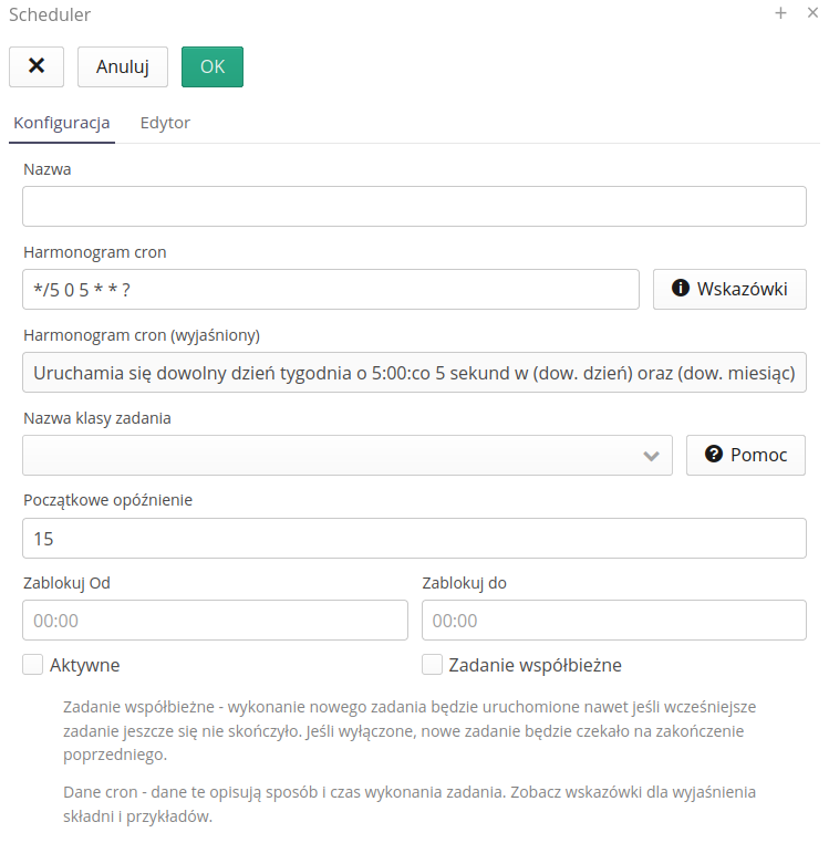
General options available:
-
Name - the name available to the user.
-
Cron scheduler - a schedule for what time a given automation will be run. This is defined using the semantics of the CRON application with very wide customizability, e.g. every 5 minutes, at 6:15 every day, every other day of the week, etc. Details and examples are available by selecting the Help button next to this section.
-
Cron scheduler (explained) - due to the CRON format, not every user is always able to define it. Therefore, the option to clarify the schedule is available. Automatically, after entering a CRON rule, the system converts its format into a format understandable to the user. In case of an invalid CRON rule, the system returns an error and makes it easy to quickly correct the rule. The system tries to describe individual records in detail and detects most errors in the CRON record.
-
Task class name - selection of the automaton. The skeleton of the automaton operation is defined by AMAGE programmers. The list of available automations and their full documentation is available in the Help Portal in the How to Do section. Abbreviated documentation is available through the Show button on the same line. Selecting the Copy button will transfer the sample configuration to the editor speeding up the first use of the
-
Initial delay - defines how much the automaton should wait after a restart of the scheduler coordinator to start. Useful when you don’t want the automaton to start immediately after application start (e.g. after server restart, when other elements are not ready, e.g. network connections).
-
Active - scheduler activity flag. If it is disabled then the automaton will be active and executed. Turning it off deactivates it. NOTE: Remember to restart the scheduler coordinator !
-
Current Task - enable allows multiple automatons of this configuration to run in parallel. If the execution of a given automaton takes, for example, 1 minute (long-lasting operations, data generation, etc.), then if we have disabled this flag and set the scheduler to run every 30 seconds, the system will NOT allow two instances of the scheduler to run in parallel and will wait for the completion of one before it runs another (generation time 1 minute, run time 30 seconds). If the flag is enabled then the system will run two instances of this scheduler in parallel, which may (but need not) affect each other.
-
Block from and block until - the ability to specify hours when the machine will not work. This can be useful when the systems to which we want to communicate are unavailable at certain night hours (e.g. backups, restarts, etc.). This option avoids unnecessary communication attempts and connection errors.
Editor - configuration editor. In it, we define additional data, parameters for the automaton. After selecting the appropriate machine, the system configures this data. They are available in two forms. A text editor with any way of entering all parameters.
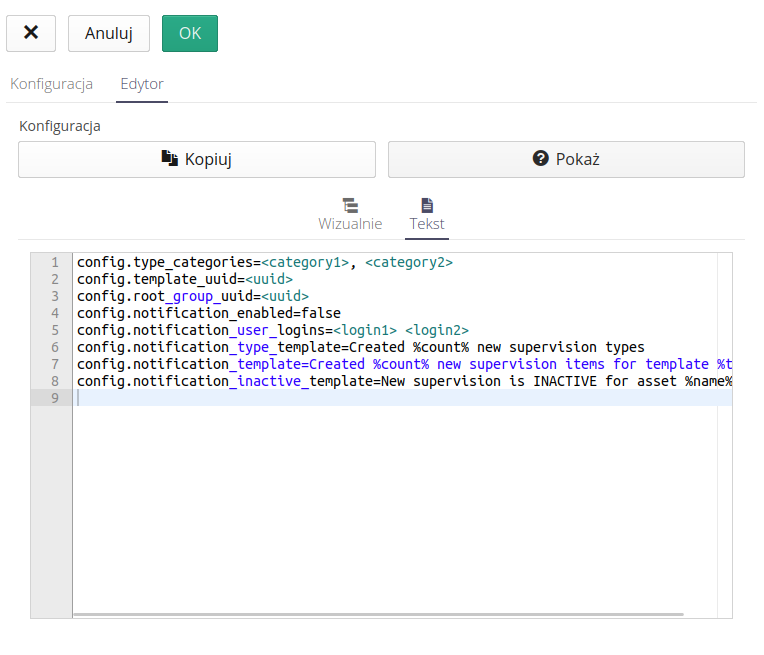
and a visual editor where each option has its own data editor.
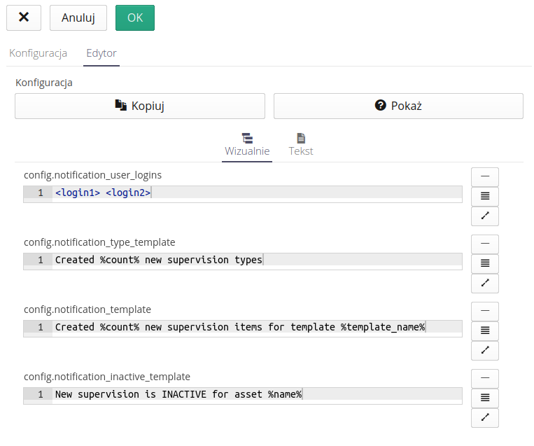
Buttons next to each element allow you to select the appropriate editing field or open an editor with syntax highlighting of markup and preview of the result in HTML form.
Such editing makes it much easier to edit fields that may contain a lot of text and newline characters, e.g. email body texts or a similar automation option. With such an editor, we can visually edit the parameters and immediately preview the result that the system will generate from such formatting.
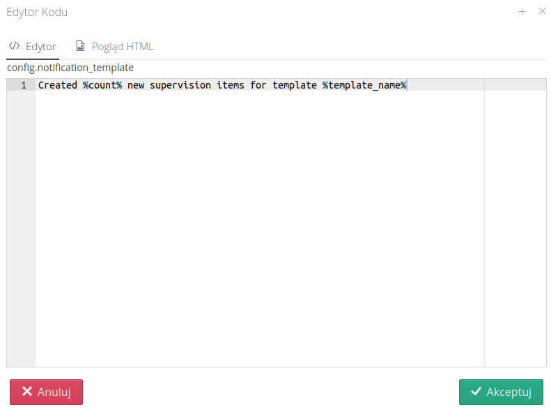
Preview of scheduler operation
Once started, the automation works independently. In the system in the configuration section, there is an aggregate view of the logs from the automation systems, i.e. from the scheduler, from events and from the integration ends. Everything is available in the documentation of the configuration section.
Automation for individual modules
The schedule view in the configuration section allows you to view all schedules defined in the system by all users. However, a view has been made available for each module, which allows you to configure events and schedules for a given functional module. This is done by a dedicated lightning bolt button, which is available in the main module views.

Using it, we can access the event configuration and schedules for a given module. In the case of the 'Schedules' module, all schedules defined in the system are available. For other modules, only events defined for that module are available.
| In order for a user to access the configuration of individual elements (schedule or events), he or she must have the appropriate permissions. If there are no permissions, only the item that is available to the user will be visible after entering the view. Of course, the user must also have permissions to access a particular functional module. |
After selecting an automation action, a window is displayed that allows you to configure individual automation elements. The list shows all schedules defined in the system. Only active schedulers are processed by machines.
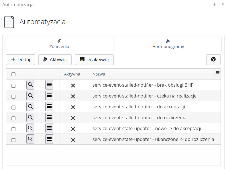
Available actions for schedules:
-
Add - adding a new schedule
-
Activate - activate the schedule and start its execution
-
Deactivate - deactivates the schedule and stops its execution
-
Help - access help for the schedule
The context menu of individual schedules allows access to additional actions:
-
Restart - restart the schedule, i.e. restart and load the configuration
-
Run once - run the schedule once without having to wait for execution according to the schedule’s time rule
| Creating a schedule, editing it and activating/deactivating it causes the schedule to be restarted and the configuration/data to be reloaded. However, if we do not want to wait for the schedule to run automatically according to the time rule, we can select the 'Run once' action and the schedule will be run once. This makes it easier to test and validate your configuration. |
| Some schedulers, after performing an operation, save their state in the system memory, e.g. the number of the last processed document. Therefore, running such a schedule multiple times at one time may cause errors in the scheduler operation and, for example, failure to deliver data (because the data has already been processed and a trace about it has been saved in the configuration). In such cases, you should pay attention to your schedule configuration and use appropriate safeguards. |
Operation logging and preview
Detailed information about the operation of machines and events is available in the logs. Using the log viewer, we can view machine operations and progress in event processing.

Detailed log preview allows you to view event logs that have been recorded in the system.

Interface for accessing historical data
Interface showing the history of data changes in the system tables. It allows for reverse analysis of data saved/modified in the main objects of the system. With its help, we can see a snapshot of information about individual objects.
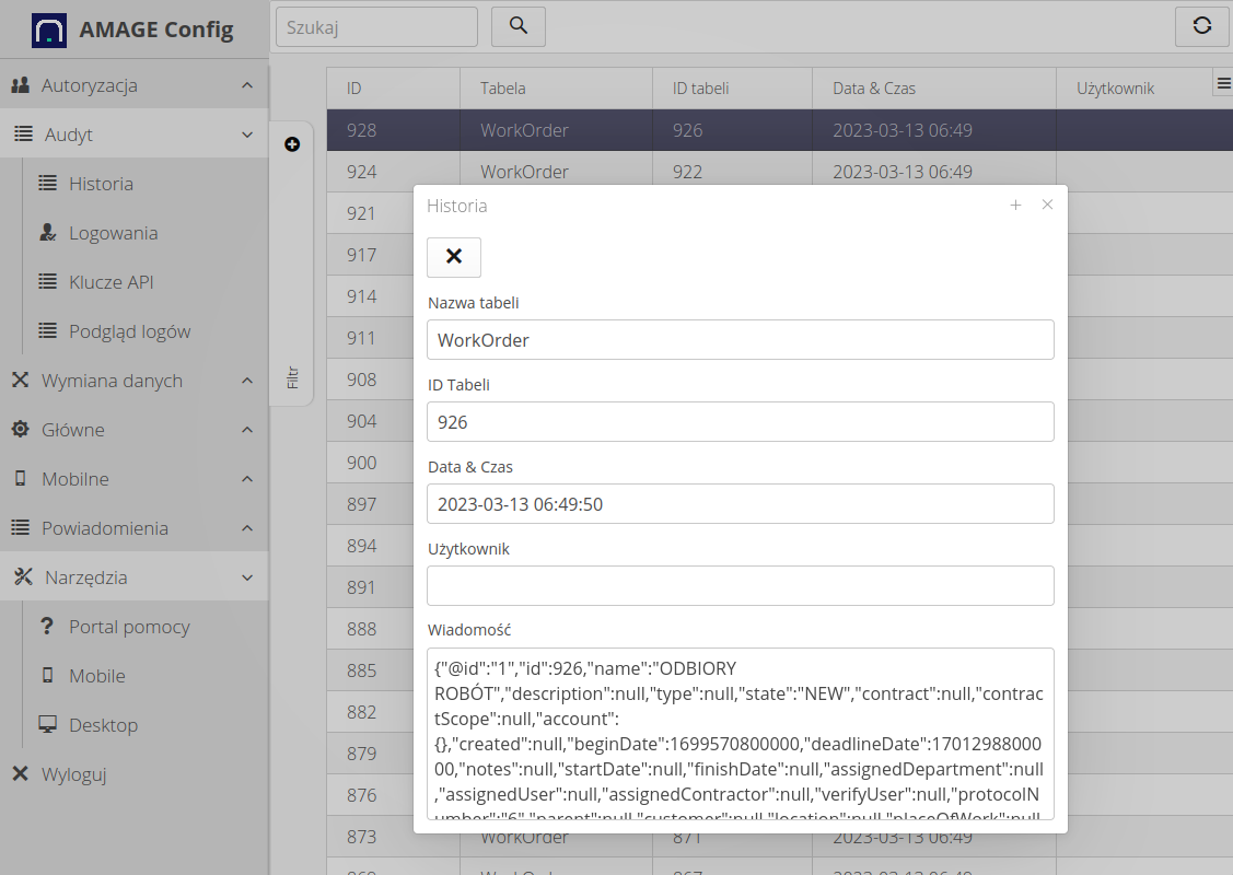
| Due to the amount of data and its retention, only key facilities have a record of historical data. |
Internal systems log viewer
The system includes a log viewer of the application’s internal systems. The application has several systems that generate actions in the background and are used to automate system operation. These components are:
-
Scheduler/Automations - that is, events generated according to a set schedule. These can be integrations to external systems, automations of service event transitions, downloading energy data from energy exchanges, etc.
-
Integrations - Integration endpoints that deal with EDI document processing, integrate with external databases, etc.
-
Events - An automatic response to a change in system parameters, e.g. a change from one service event state to another.
All of the above-mentioned elements can be defined in the appropriate sections of the configuration interface. Each of these systems generates logs informing about its operation and possible errors/problems in processing.
Using the log viewer available here, we are able to view the logs that these systems generate. To access it, call the Log Viewer action from the Audit section in the configuration.
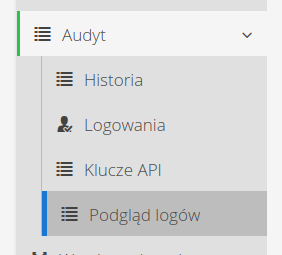
Once passed, a list of available logs appears, which we can view/monitor.
List of logs
-
Integrations - data from the integration system
-
Schedulers - data from scheduling machines
-
Events - data from automatons responding to changes in objects
| Not all logs are available in every instance. In those where some systems are turned off, logs from this area do not appear. |
The log view is divided into two sections. The log stream selection and the actual data preview.
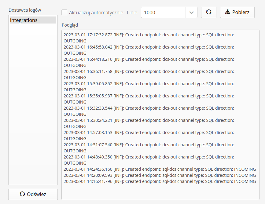
In the view of the individual log stream, we have available actions:
-
Update automatically - enabling it automatically refreshes the log stream
-
Lines - visible lines from the log stream. The number of lines is specified.
-
Action: refresh - the ability to manually refresh the log stream
-
Action: download - download logs as a text file
| The log download always downloads the full available log stream. The logs for each stream after reaching a certain size (10MB) are automatically replaced with a new stream. |
Access key management interface
An interface for managing keys to access the WebService interface via a generic programming API. Documentation for the API is available in the developer documentation section. This is where we manage and generate the API keys.
The call to action presents a list of available API keys, information about the key value part (key, UUID) and the activity, generation and expiration dates of the key.
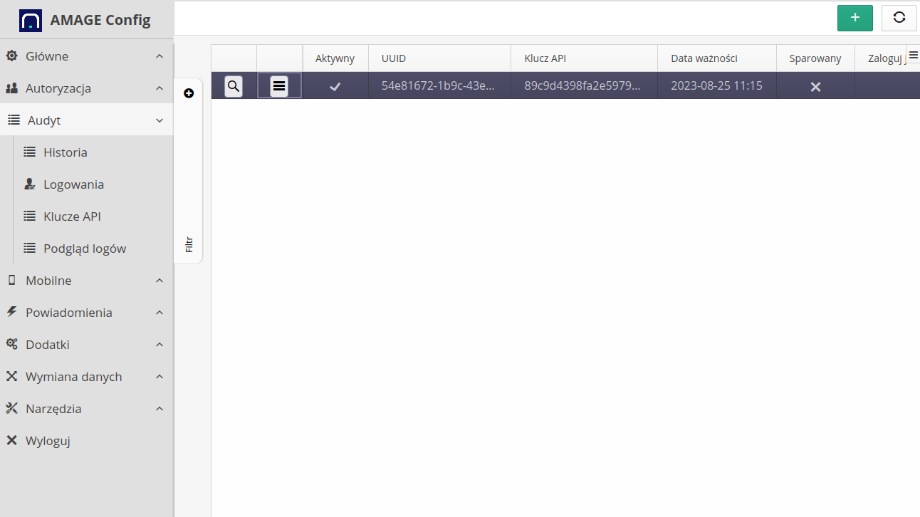
| The key is active if the expiration date exceeds the current system date. In addition, for mobile devices, pay attention to the "paired" flag, which is used in some applications in the pairing procedure, i.e. once the key is paired, it is not possible to reactivate this key on another device |
For each API key, contextual actions are available that allow you to edit, delete and quickly activate/deactivate the key.
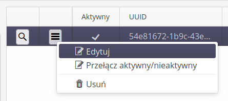
Filtering mechanisms are available in the list to display active or inactive API keys
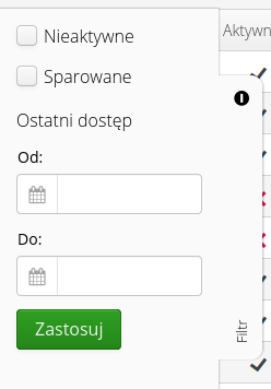
Adding a new key
The key can be added through the Web interface. To do this, select the (+) button action. This brings up the Add New Key window.
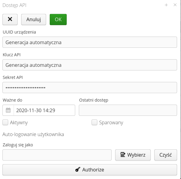
Data of the type UUID of the device, API key and its secret will be generated automatically by the system when saving a new key. The user has the option to enter expiration dates and flags indicating that the key is active and paired.
If you edit an existing key, a window with information about the key is displayed after selecting it in the main list. The API secret is displayed after selecting the 'Show' button. In addition, through the action Transfer we have the ability to change the expiration date of the key which means changing its activity.
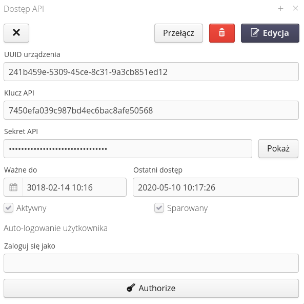
| Documentation of the use of the API key and the generation of signatures for individual WebService queries is defined in the development documentation provided at the start of the system integration/implementation work. |
User auto-logging
The system allows a selected user to automatically log in on a specific browser. This allows parts of the system interface to be available without logging in, e.g. in conference rooms, visualizations, dispatch panels.
| The mechanism is based on information stored in the memory of the web browser. Properly prepared data including information about the API key and secrets are stored in cookies of the browser. |
To enable such logging, define a user in the definition view of the selected API key, who will be automatically logged in if the browser has the appropriate authorization data. The user selection is defined in the API key view.

| It is not possible to add/use for authorization a user who has Super-Administrator privileges due to the fact that such a user has all possible privileges and the mechanism of access profiles for such a user is bypassed. |
After selecting and saving this information, you can select the Authorize button on the browser, which will be the target web browser for automatic login. The system will automatically go to the key pairing view. If the user has access (is logged in) then the system facilitates the pairing by automatically going to the pairing window. If you do it manually then go to the address (in the context of the application) config#!apiaccess-token-entry.
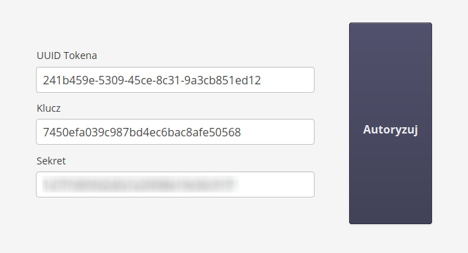
The window allows you to enter the API key identification data and validate it. Once the data is validated, a suitably crafted cookie is saved in the browser’s memory and from then on the application will automatically log in the selected user
List of all logins to the system
The list of all logins allows you to view the login history of all users in the system. The list shows logins to the system via Web application (any interface) and via Legacy Desktop application (installed on computers). The 'source' column specifies with which system the user logged into the application.
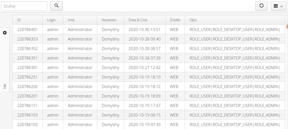
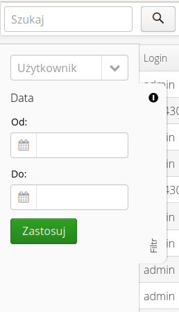
Use the search filter to specify a date range or a specific user for the general view.
| The login list does not include logins for offline mobile devices. The Fx app feedback does not synchronize this information. Online logins, on the other hand, are displayed in this view. |
The window contains information about the login date, user, from what source the login occurred (Web/Mobile application, application installed on computers or other). In addition, the Description column shows what roles the user has:
-
ROLE_USER - the user has login privileges to the mobile interface
-
ROLE_DESKTOP_USER - the user has login privileges to the desktop interface of the Web application
-
ROLE_ADMIN - the user has permission to log in to the configuration interface
Dedicated mobile devices
Definition of dedicated mobile devices - devices working with AMAGE Fx or AMAGE CE application on dedicated devices. Possibility to work in offline mode. The device list allows you to define devices and configure them.
After entering the main menu of the Mobile → Devices configuration, a list of all defined mobile devices is presented. Adding a new device is done by selecting the (+) action.
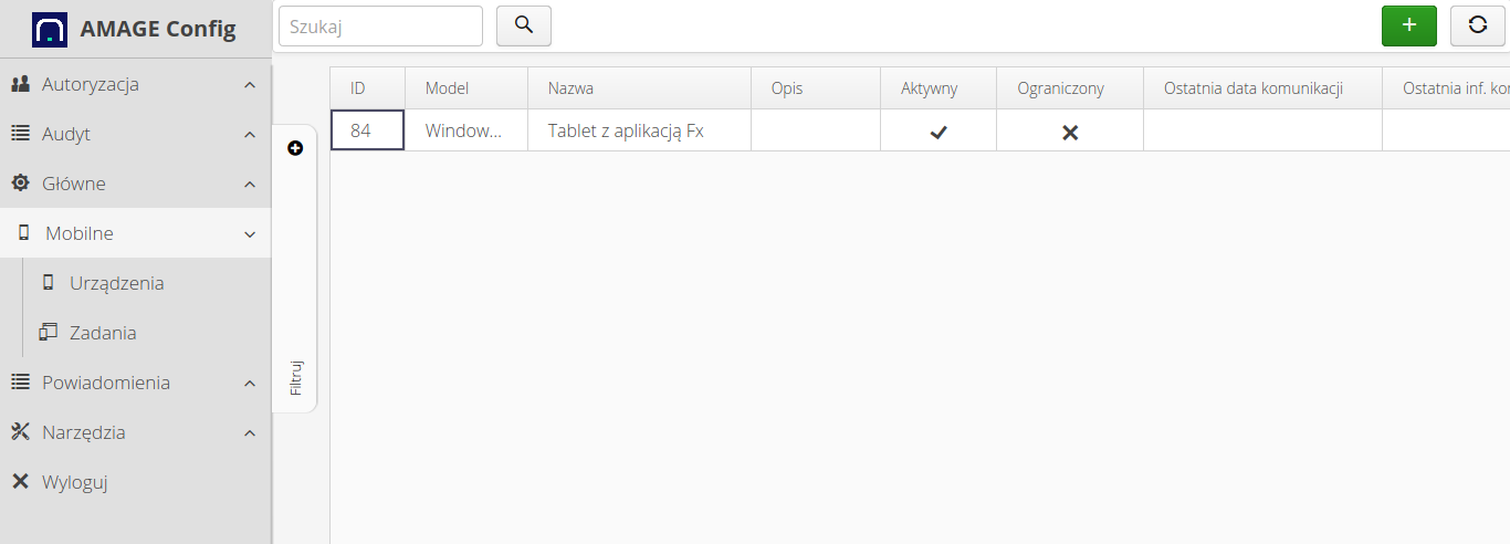
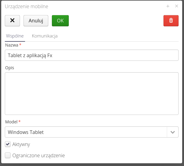
The definition of a new mobile device allows you to specify its parameters and settings.
-
Name - the general name of the device visible in the summaries
-
Description - additional description of the device, e.g. owner, etc.
-
Model - the device model that is supported. In the case of the AMAGE Fx application, select
Windows Tablet, in the case of the PVD application, selectData Aggregator -
Active - whether the device is active, i.e. whether we accept communication from this device
-
Restricted device - when this flag is enabled, only mobile tasks that have been explicitly assigned to this device are visible through it.
| The restricted device flag is intended to allow you to specify a detailed mobile task along with a slice of the data that is being synced for that device. This makes sense in the case of devices that are handed over to, for example, subcontractors or contractors to perform specific activities, e.g. inspections. In this case, we ensure that a given mobile device will only receive the information that we assign to it. |
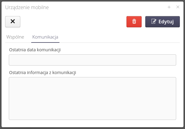
The technical information tab stores information from the PVD application regarding the last date of communication and the last information regarding communication with this device. This facilitates possible diagnostics.
After adding a device, additional options appear in the context menu of the tabular view:
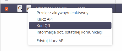
-
Toggles active/inactive - enables/disables communication with the device
-
API key - displays the API key data. This gives you the opportunity to copy this data and enter it, for example, in the data aggregator in its configuration
-
QR code - displaying the QR code with the configuration data of this device. The AMAGE Fx and AMAGE CE Lite applications have the ability to scan this code and automatically configure it based on the data contained therein.
-
Information on last communication - displays communication details in an additional window. This allows you to view the data in a larger view.
-
Edit API key - allows you to edit the API key associated with a given device.
| Each mobile device, at the time of its creation, also automatically creates one pair of API key data, which is used to authorize queries between the device and the server. For more information about API keys, see the configuration documentation. |
Tasks for mobile devices
The definition of tasks/data ranges for dedicated mobile devices allows you to specify the data range so that they work only on a separate part of them. The interface allows you to control the data sent from such devices. In the case of devices working offline, it is not possible to synchronize the entire main database due to its size. In this case, the logic of mobile tasks was created. They fulfill two roles:
-
Define what data is to be sent in this task to the mobile device
-
Storing information sent from mobile devices before their integration with the main database (changelog).
In the configuration view in the Mobile section, we have access to mobile tasks through the Tasks action. After selecting it, we are presented with a list of mobile tasks and their statuses.
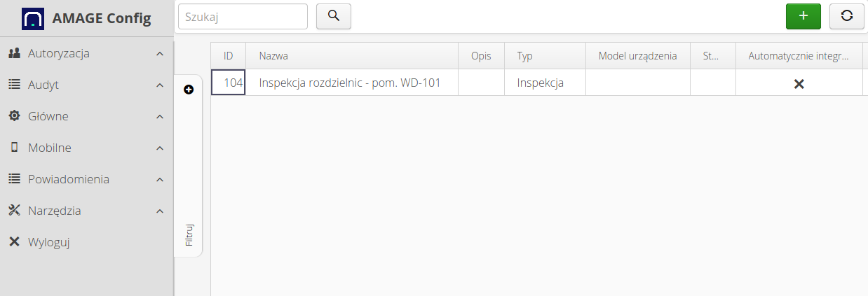
We can create a mobile task using the + button, editing is available directly from the list of tasks. When creating/editing tasks, we can specify the basic data:
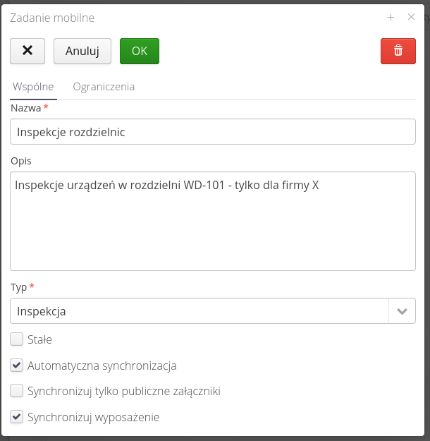
-
The name - task name - will be displayed on mobile devices
-
Description - detailed description of the task
-
Type - task type - general, inspections, rounds
-
Status - the current status of the job registered, available, on device, returned, closed, canceled, permanent
| Depending on the task type, it is displayed on specific devices. For example, the AMAGE CE Lite application supports only 'Supervision' tasks. |
Additional task flags allow for additional control:
-
Permanent task - the task will not change its state after being received from a mobile device. This allows you to keep this task always available for mobile devices.
-
Automatic synchronization - automatically synchronize data sent from a mobile device to a central database
-
Synchronize only public attachments - during synchronization, if the user requests attachments/files associated with objects, only files with the
Publicflag will be sent. A useful option when transferring the device to an external subcontractor/customer, etc. -
Synchronize equipment - during task synchronization, resources of the 'Equipment' type will also be sent to the device. Useful for performing remote offline inspections. In this case, we can also choose, for example, a measuring device with which the inspection is performed.
In the second tab of the mobile task, information about the limitations of the given mobile task is available.
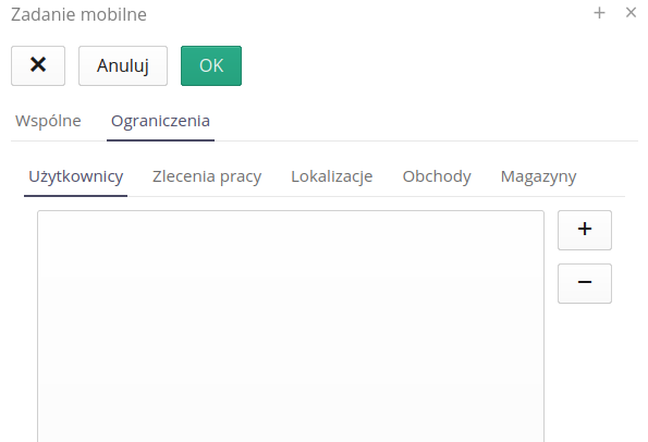
Restrictions may apply to the list of users uploaded to the device, resources from only selected locations, only specific work orders and their associated objects, and others according to the list.
-
Users
-
Locations
-
Work orders
-
Inspection rounds
-
Warehouses
The system tries to intelligently select the transmitted data in accordance with the selected parameters. For example, selecting location A will allow you to send to the mobile device all devices/resources in this location AND child locations (places/rooms).
|
For each task we have a context menu with actions available:
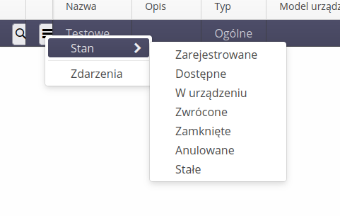
-
State change - an explicit change of the state of a given task. Usually, the status change is carried out automatically by the communication process, e.g. after sending the completed task, the mobile device automatically changes the status of the task to ready for integration.
-
Task events - view of task events
Mobile task event
Each task as described above also serves as a storage for data sent by mobile devices. When working offline, mobile devices perform work and create new entries completely separate from the central system. So-called change logs (journals) are created on the mobile device. They define what has been changed/created outside of the central database.
During synchronization, this data is sent back to the central system and the system updates the data in the central database based on this change log. This is necessary because the central system must ensure the uniformity of data in the central database. One example of such troubleshooting is updating a record that has been deleted from the central database by, for example, another device while working offline. In this case, the data sent from the mobile device must be properly processed.
The mobile task event view shows exactly these data packets sent by mobile devices along with detailed data. The list is divided into two sections. The first is the individual communication and the second is the content of the log sent in each communication.
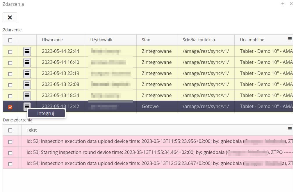
The system automatically integrates all the data that is possible for such an operation. Events that have any problems can be updated on their own using the action available in the context menu of the selected event. After successful integration, the system changes the status of the event to 'Integrated'.
List of report definitions
The list of reports in the configuration system allows you to specify the visibility of reports in the system and their visual configuration (e.g., the appearance of the default report template).
The list of available reports shows all reports currently available in the system. These reports can be system reports or user-defined reports.

| The report list allows you to define any number of new reports for definable data types. Their use and availability depends on the implementation of individual modules. |
After selecting a report, a window of detailed information about the report is presented.
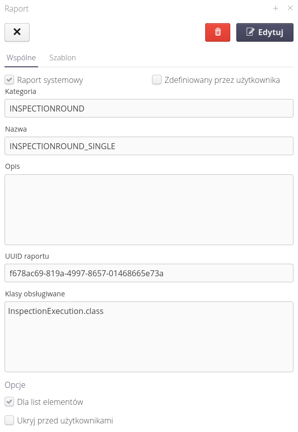
General information is presented there, a description of which data object the report belongs to, its unique identifier (used in referring to this report in generators). In this view we can specify whether the report is available for a single item or for groups of items. The option also allows you to hide the report from users - in case for a given instance the report is not useful or not used.
The template tab allows you to define your own report design. We upload a ZIP archive of reports to this place, which are replaced during generation.
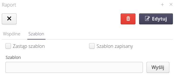
This approach allows you to modify the appearance of the report by replacing the default report appearance in the system. Due to the fact that reports can consist of sub-reports to this place we upload a ZIP archive with all reports/sub-reports that we replace.
| Detailed information about report names, available fields, appearance and configuration can be found in the Help Portal in the "How to" and "For Developers" areas. The free tool/report designer is also described there. |
Report tab
Each report can have tabs. Bookmarks are an additional way to customize the look and settings of a report. Reports by default have their configuration parameters displayed in the report filter windows. Bookmarks allow you to save a selected set of configurations and run them again without having to fill in the filters once again. An additional function of a bookmark can be the definition of the report’s appearance. Sometimes it happens that when generating reports for a certain type of object (e.g. Inspections/Service Reports) we want to change the appearance of the report and adapt it to an external recipient (customer, department, etc.). Using tabs, we can take advantage of this.
When the Tabs button is selected, all defined tabs of the report are displayed.

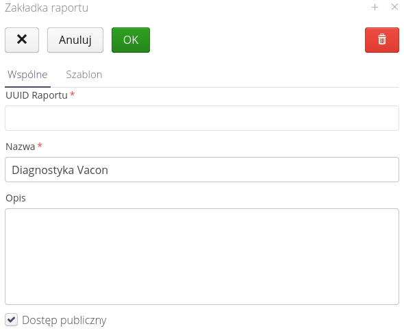
In this window you can add new tabs or edit existing ones. Editing existing ones allows you to define general information in the General tab
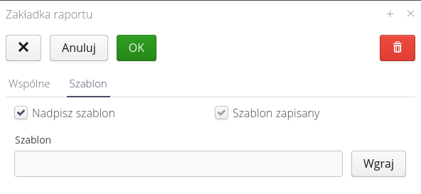
And define the appearance of the report generated using this tab. The functions are the same as in the report definition window.
Configuration - general data
General configuration data necessary for proper operation of systems. Determination of basic parameters and settings is realized through this view. It is accessed through the main menu 'Main' → 'System'.
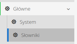
The settings view is divided into two sections 'Common' and 'Counters'. The common section contains the main system settings affecting the application.
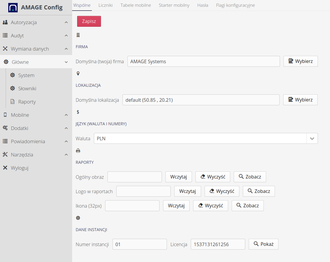
Available configuration options:
-
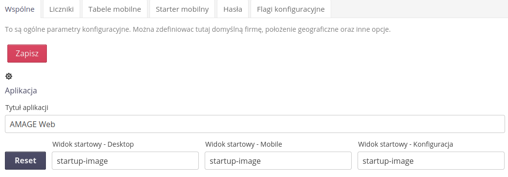
Application title - the title of the application displayed in the title bar
-
Default start views - in which view we start the session in each area
-
Default location - select the default location. This location will be shown as the initial location in all windows where geographic location/plans are required. It is usually set on the view of the workplace, plant, construction site. This allows you to quickly specify additional locations without having to constantly search. NOTES. The default location is set to (0,0) in the Atlantic Ocean.
-
Currency - select the currency displayed in the application in those places where price information is stored. NOTE: This setting is used only for data formatting. No currency converters are used.
-
Images - the ability to upload images/logos used in login/information windows and separately an image used as a company logo in reports.
-
Instance data - instance data resulting from the license and deployment settings. The license applies to data set during deployment by AMAGE Systems. The instance number is assigned by system administrators.
Using the default start addresses, we can specify the address at which we start the session for the mobile, desktop and configuration views. To change it to any other, use the end of the address and enter it in the given field. For example, to start the configuration view from the system data configuration, we will enter config-desktop-system because the address of this area is: config#!config-desktop-system
| The system number (derived from the license) and the instance number are used during the generation of unique 2D/Dash codes in some modules. It is very important that the instance number is unique among all instances running for one customer. The customer has the option to determine this number independently. |
Counter data
Counter data is used to indicate to the system which counter definitions to use when generating unique numbers for documents created in the system. In this area you define which counters the system should use when generating documents from the order/supply area, which ones for warehouse operations and other systems (service events, etc.).
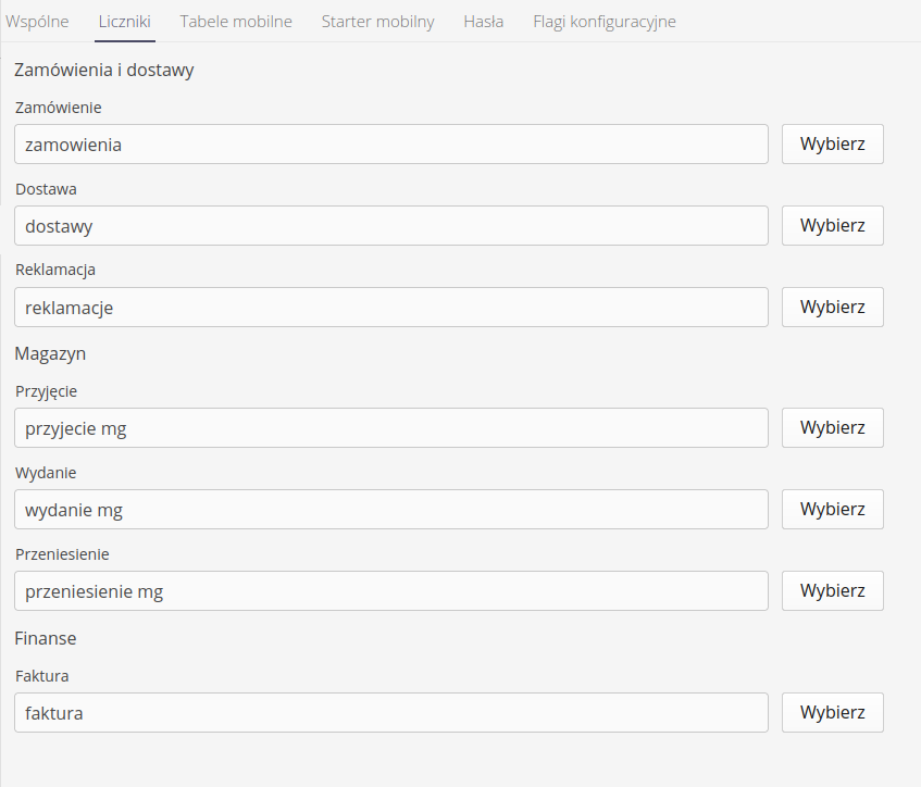
| The counter settings are used for document generation, where the user chooses to automatically assign consecutive document numbers. |
Mobile tables
The configuration of mobile tables can be adjusted in each instance separately. Due to the small amount of space in the mobile interface (especially on phone-type devices), it is not possible to present all the data in the lists available in this interface. Each instance of the system may also have different needs for showing data. For example, one instance may use type order numbers and another may not. In the former case, it is important to show this number in the interface (in the list) and in the latter it is not necessarily so.
By default, the system, if it does not have a mobile table view configured, presents the following items in such a table.
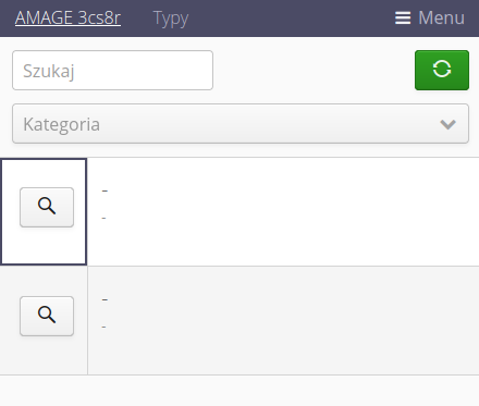
In the system configuration section, there is a Mobile Tables tab and there you can configure the views for the various lists available in the mobile interface.
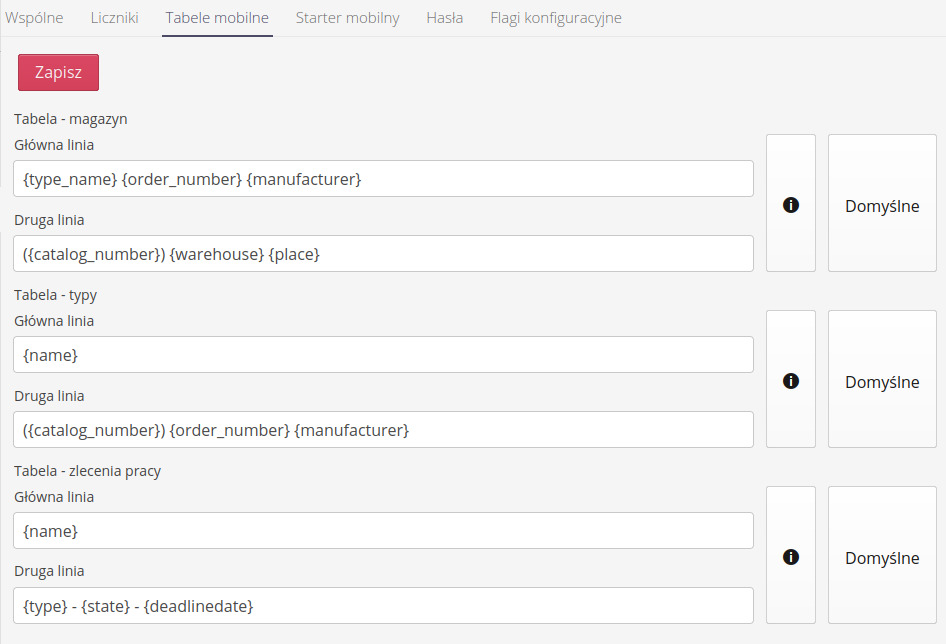
Each list has two lines - a main line and a secondary line. Each of them can be separately configured using fields for entering your own words and keywords (eng. placeholder) in which the system will enter the relevant parameters of the object. In this way we can freely configure the visibility of information.
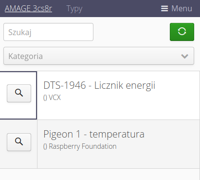
An example view of the types already after the default configuration:
Mobile starter
The mobile application has the ability to enable the start panel when launching this application. The system allows you to freely configure the available buttons and actions provided there. Using this view and tab, we can configure any view.
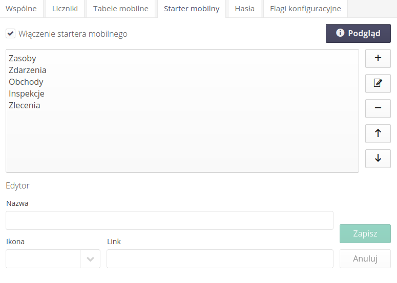
When the Enable Mobile Starter action is enabled, it will be used as the starting point for the application. Once you enter and select the application name in the top corner of the mobile view, the system will go to this view and allow you to quickly navigate to the selected actions.
To define any action, you need to add a new item, enter the text you want to display, select an icon and specify the address to which the system will be redirected when you select this action.
This approach allows any view configuration taking into account even additional filters and settings i.e. we don’t have to go to the general view of work orders but we can immediately use such a button to go to work orders that are in Scheduled state. To do this in a web browser we go to the mobile view (see the general initial instructions on how to force a mobile view), then go to the view we want to pin to the button, set all the filters and copy the final part of the address as in the example below.

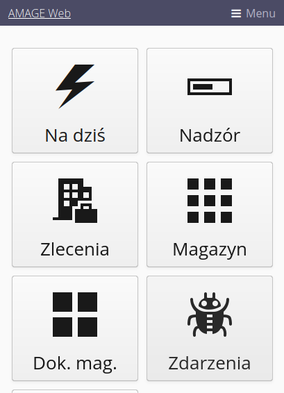
Using the Preview button, we can display the configured starter buttons as they will be presented in the mobile application.
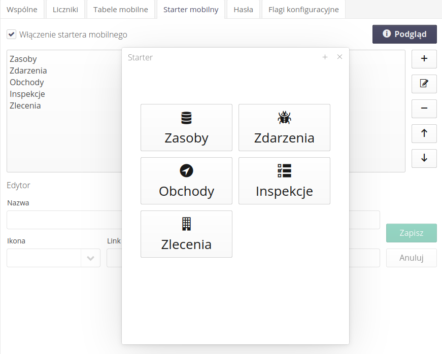
After activating such options, the starter may present itself as follows:
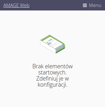
If we enable the starter but do not define any tile, the default view will appear with information about the lack of startup elements.
Security
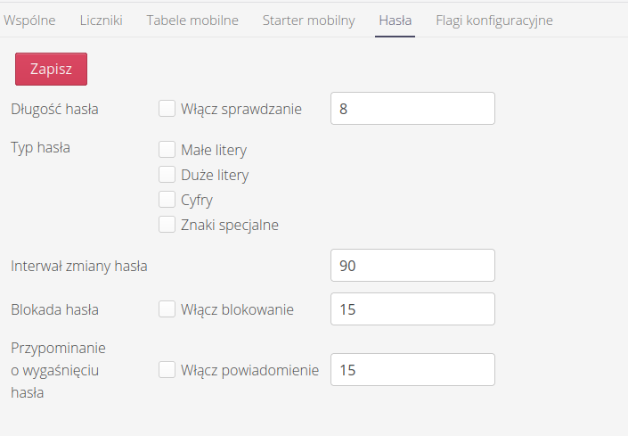
The system allows you to define a password policy for local users. After going to the configuration view and selecting the Passwords tab, we can set the password security policy. By default, the policy is disabled which allows the user to set any password.
Options available:
-
Password length - minimum password length
-
Password type - types of characters that must occur in the password (upper/lower case, etc.).
-
Password change interval - every how many days the password must be changed
-
Password lockout - after how many days after the password change interval, the account will be locked if you do not change your password
-
Password expiration reminder - how many days before the password change interval expires, a reminder should be sent to the user to change the password.
| A locked account can be unlocked by an administrative user, who will set a new password and login settings in the configuration interface. |
| The password policy applies only to local users who authorize using passwords stored locally in the AMAGE database. It does not apply to corporate users who authorize themselves in external systems such as Active Directory/LDAP. |
In the case of systems that have the ability to log in using corporate accounts enabled, e.g. via Azure Entra ID, we can define additional behavior in the section regarding corporate login.

Options available:
-
automatically create users - only for corporate accounts. After successful logging in, a default user is created in the remote system without any other permissions except the ability to log in to the system. This makes it easier to configure users later.
-
domain name for corporate logins - when provided, the username in the AMAGE system will be the name sent by the authorization system, omitting the provided domain. If the user logs in as admin.test@domain.com, then if the domain is configured as @domain.com, the user will be entered in the system with the login
admin.test. -
list of access profiles. List of access profiles separated by a comma. These profiles will be assigned to the newly created user.
Configuration flags
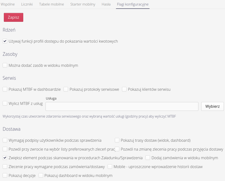
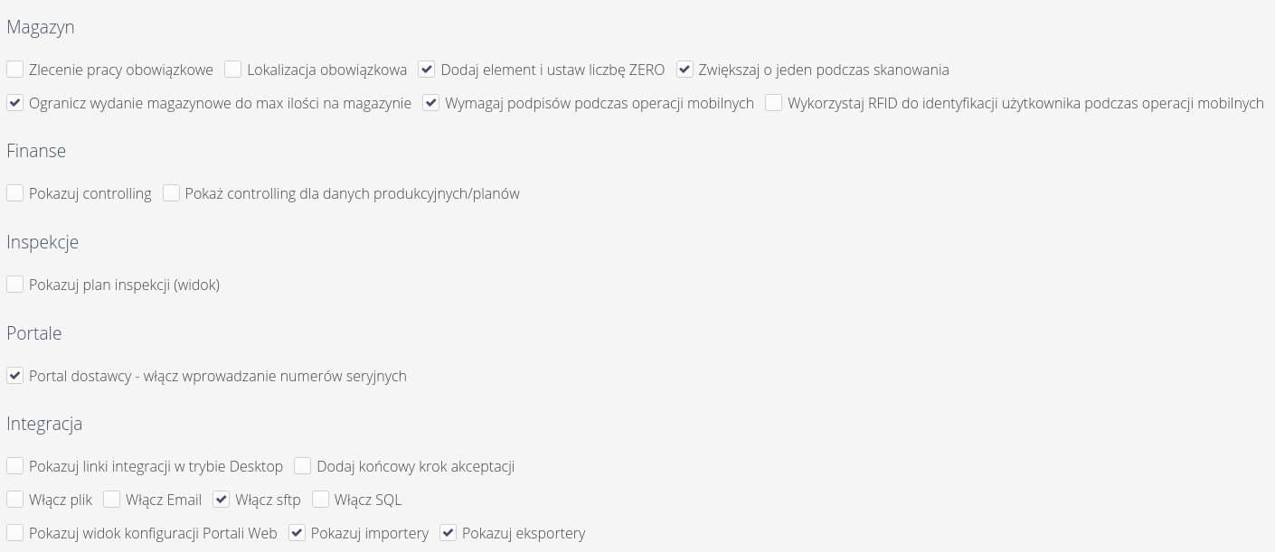
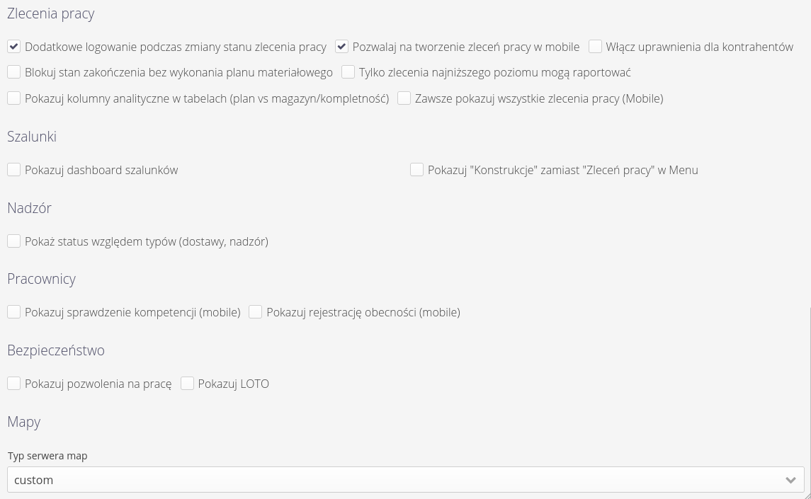
Configuration flags allow you to set specific system behavior for individual modules. Usually these settings are enabled during the initial implementation of the system and determine how functions behave in the system, e.g. whether electronic signatures are required during delivery checks. Using this view, we can also determine the visibility of certain sections in the system (hide if they are not used in a particular case, for example).
| The settings should be treated as a significant change in the behavior of the application, and it is advisable to approach changes to these settings with appropriate caution, as they can change both the behavior of the application and also increase/decrease the visibility of data on the system for certain users. |
Configuration - dictionary data
Dictionary data is accessed through the dedicated 'Dictionaries' main menu. After enabling this view, a list of all available dictionary configurations in the system appears in the form of a table of buttons.
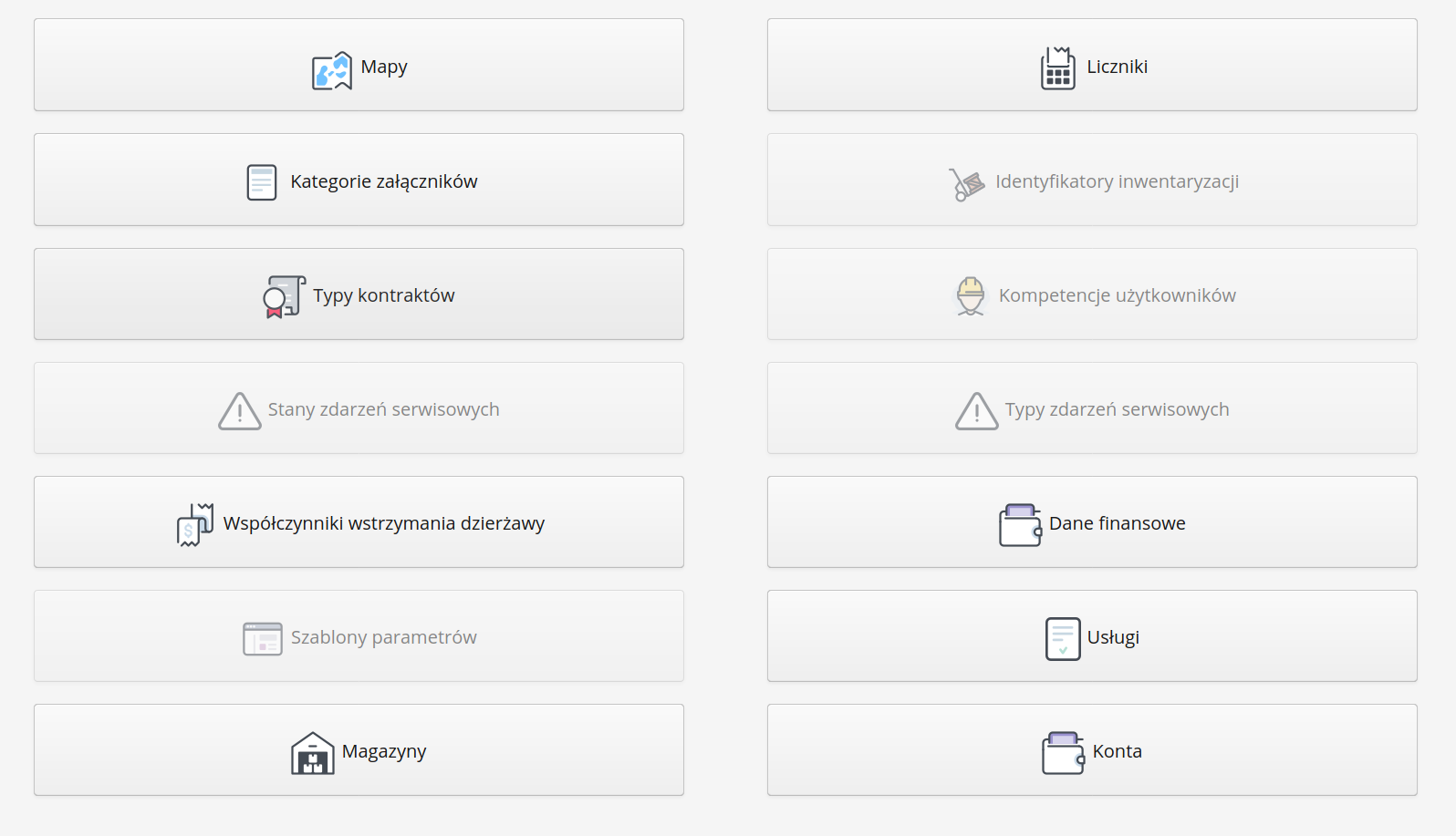
| The visibility of the buttons depends on the available functions in the system resulting from the license/implementation privileges. |
Configuration - billing accounts
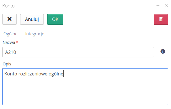
The window defines accounts in the system. Accounts in the application are the connection between the AMAGE system and external finance and accounting or billing systems, e.g. with external suppliers. An account is an identifier by which we link objects in the system (e.g., work orders, warehouse storage locations) with corresponding cost centers or billing groups in external systems.
The list presents a complete list of billing accounts available and defined in the system. Accounts can be created manually or created automatically when importing data from external sources (e.g. XLS files).

The billing account editor allows you to provide a name (ID) and an additional description for the account
External integrations
Integration systems allow for additional automation. In the case of EDI documents, in addition to automatic downloading of documents, it is also important to categorize them, e.g. to the appropriate cost account. To do this, the integration system has the ability to search EDI documents (deliveries, orders, returns, etc.) for keywords that uniquely identify a given cost account.
In the "Integrations" section, you can define such elements. In the following new lines, we can provide sets of texts that, found in descriptions, titles or additional data of EDI documents, will allow for the identification and assignment of the document to a specific cost account.
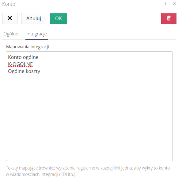
| Make sure your keywords are unique to each account. The system will select the first account that matches the keyword. |
Configuration - contract types
Contract types is a dictionary definition that allows to categorize contracts existing in the system. With the help of these definitions, the user can divide the executed works according to his own nomenclature. The list of contract types shows all active contract definitions.
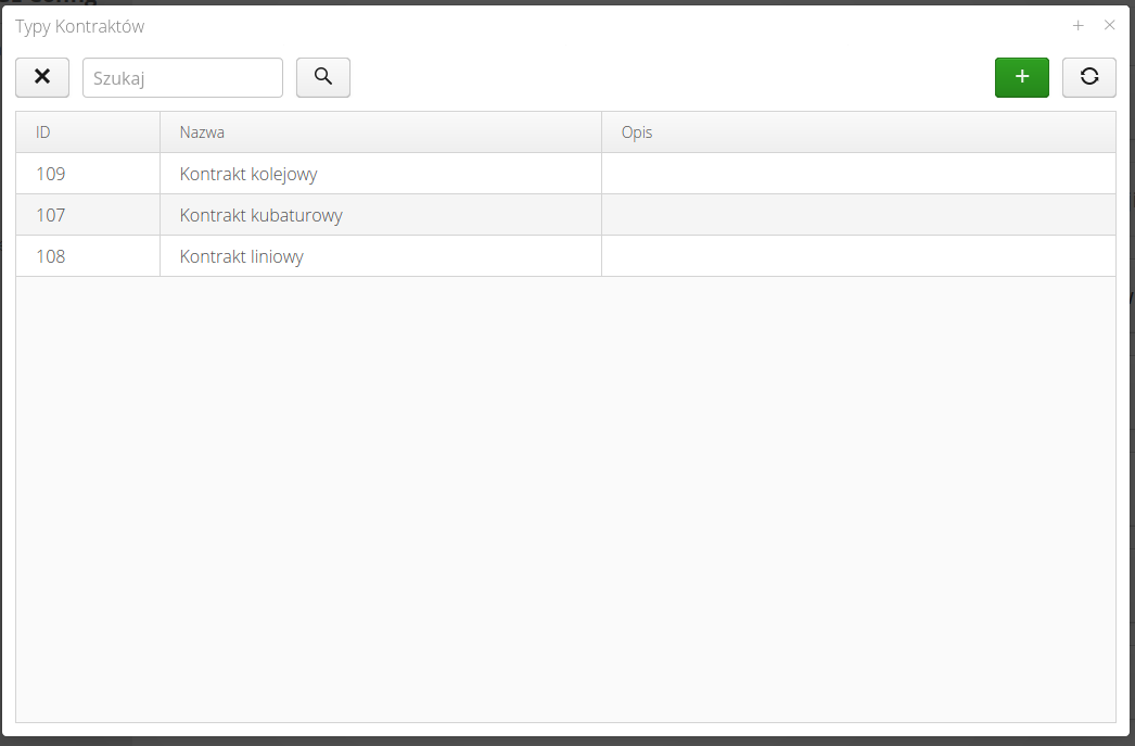
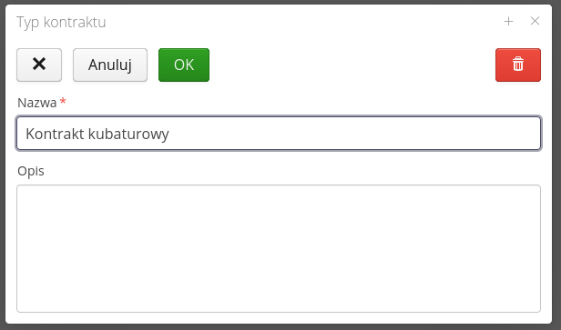
The contract type editor allows you to give it a name and additional text description.
Configuration - meters
Counters is a dictionary data that allows the system to automatically number documents, events, minutes and use the counter as a source of unique (consecutive) number with a specific appearance format. The dictionary list shows all the counters defined in the system.
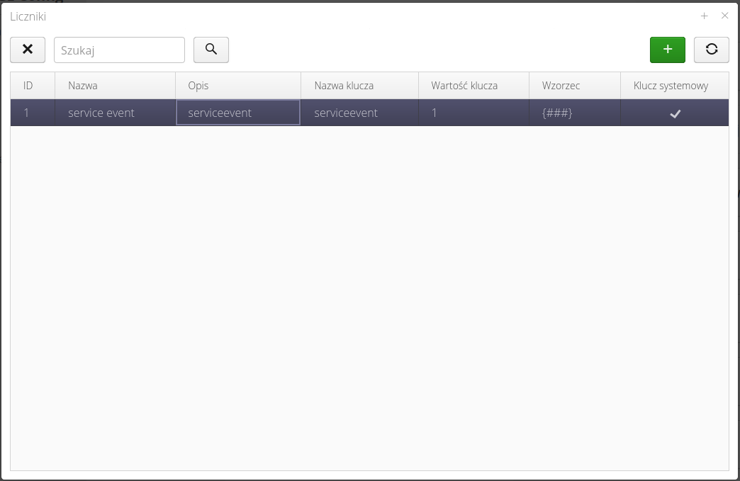
| Counters are also used internally by some system modules. Therefore, counters marked as system counters may appear in the counter list. They cannot be edited/deleted as they are used by the system. |
Creating/editing a counter displays an editor window that allows you to define the information necessary for the counter to function properly.
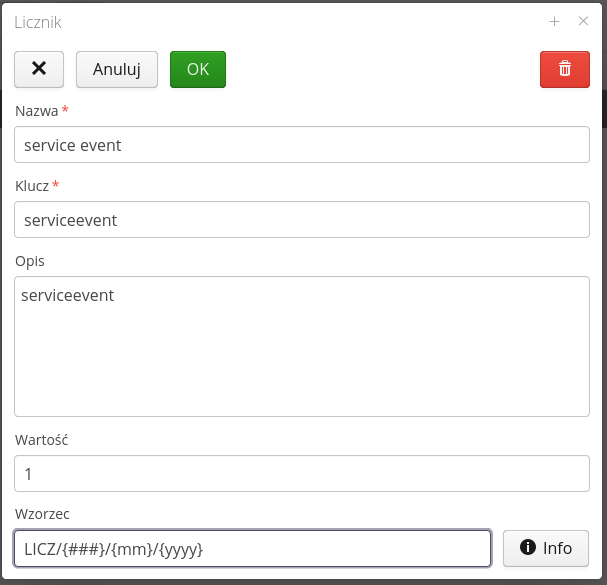
Available fields:
-
Name - The name of the counter made available to the user. It can be any text meaningful to the user.
-
Key - The identifier of a counter shared with systems or schedulers. Usually this is a key of type <identifier_name> which allows easier reference to this counter in scripts/automations.
-
Description - Description of the counter
-
Value - The current value of the counter. Default is set to 1. The counter will be automatically increased after generation. In this field you can change the initial counter value, for example, to 100.
-
Pattern - The pattern that will be used to generate a textual representation of the counter. Using it, you can place a number from the Value field within texts and additional automatic fields.
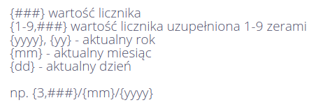
After selecting the Info button, a window with information about possible options for the pattern is displayed. This allows you to enter fields such as counter value, current month, current year or any text into the text representation generating for example PZ/1234/04/2020.
Configuration - employee competence
Interface for the definition of a set of employee competencies. Competencies can be verified during inspection work, e.g., at a construction site, or used to determine/select people with specific competencies to perform work at the plant.
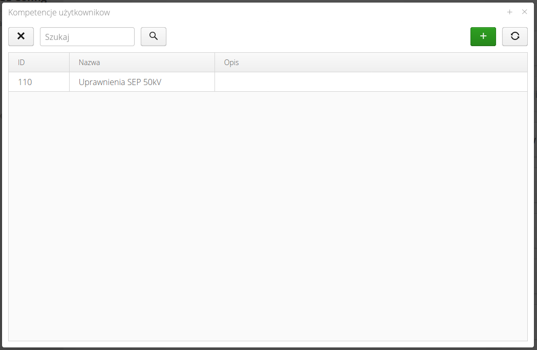
With the help of a competency dictionary, we define a list of available competencies in a given organization - this could be a set of electrical, mechanical, machine operating, etc. competencies. Competencies then assigned to an employee can be used to select competent people to perform given activities accordingly.
The list of competence types shows a list of all competencies.
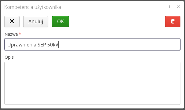
The competence editor allows you to enter is name and textual description.
| All additional parameters of the competency, e.g. the expiration date of the document, whether it requires periodic checking of this competency, etc., are defined when adding competencies for individual users |
Configuration - financial data
The financial data dictionary area contains information about financial and accounting and billing parameters used in reporting mechanisms or data generation to external systems. These data are defined for each month separately.
The list of available financial data shows all the financial data defined in the system with an indication of the period to which they apply.

The financial data editor allows you to enter descriptive data for a given financial period and specify the FRI date.
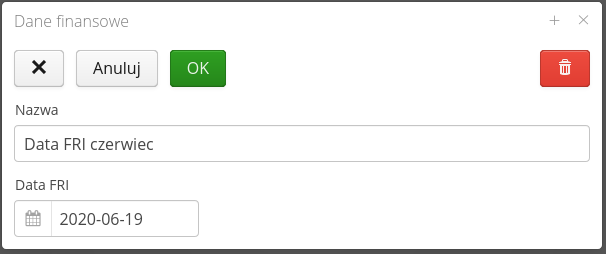
| The FRI date is the accounting date for the finances of the month. By this date, financial data must be entered and transferred in the organization to the finance and accounting cells. This date is usually the date before the end of the month, so the data from this date to the end of the month must be calculated in a different way than on the basis of available documents (approximated, projected, etc.). Based on this date, the system can generate financial values at the end of a given month in some billing areas (e.g., leases). |
Configuration - inventory identifiers
Inventory identifiers are sets of identifiers that facilitate inventory work. The system has its own mechanism for generating unique identifiers. These identifiers are later used to uniquely identify equipment in the plant by scanning, for example, QR/2D codes with these codes. The identifiers generated in the system consist of a common part (identifying the system and the instance) and a variable part automatically incremented.
The from stock inventories are usually carried out in a location where it is difficult to access the ICT infrastructure and print space. The timing of such an inventory is also important. In order to speed up these operations, users in the system can prepare a package of badges before the inventory, print them as 2D codes and use them during quick tagging of equipment. The next step involves reading the badges and producing photo documentation. The final step is to arrange the data in the system, but this is done at any time in front of a computer screen.
The list of inventory IDs presents a list of all previously generated packages.

Using the context menu, we can enable the generation/printing of identifiers. We can also mark a given package as already printed (so as not to print/use it again).

To reserve a package of identifiers, you need to create a new entry. In it, you specify the name of the package in question (for easier handling later) and the number of identifiers that will be reserved (generated).
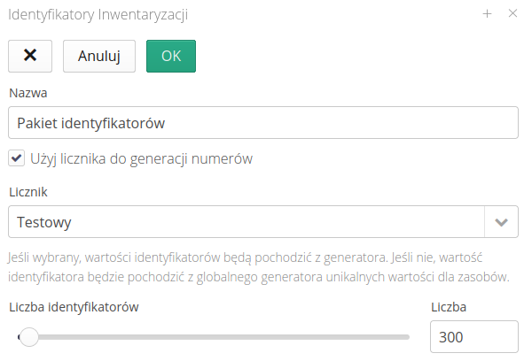
In addition to generating standard codes of the P99901-0000001 type, the system also allows you to use any counter defined in the system to generate such codes. This can be useful when, for example, we want to generate codes for the inventory numbers of a given company. Then we use a new counter with an appropriate pattern that will generate such a list of data to be printed.
Configuration - lease modifications (suspensions)
The lease withhold definition interface allows for the definition of periods in time during which no lease is charged for selected orders/components. This is used for accrual restrictions consistent with supplier contracts.
| In the case of accounting for leases/rentals of resources that are handled by the AMAGE system, continuous charging is implemented, i.e., for the number of all days that a resource (equipment, shuttering, etc.) is in possession, the corresponding amount is charged. There are events that cause interruptions in such charging. |
The list of lease withholds presents a list of all lease withholds defined in the system. This list is also available within individual objects (showing withholdings for that object only). The list available in the configuration module shows all defined withholdings.
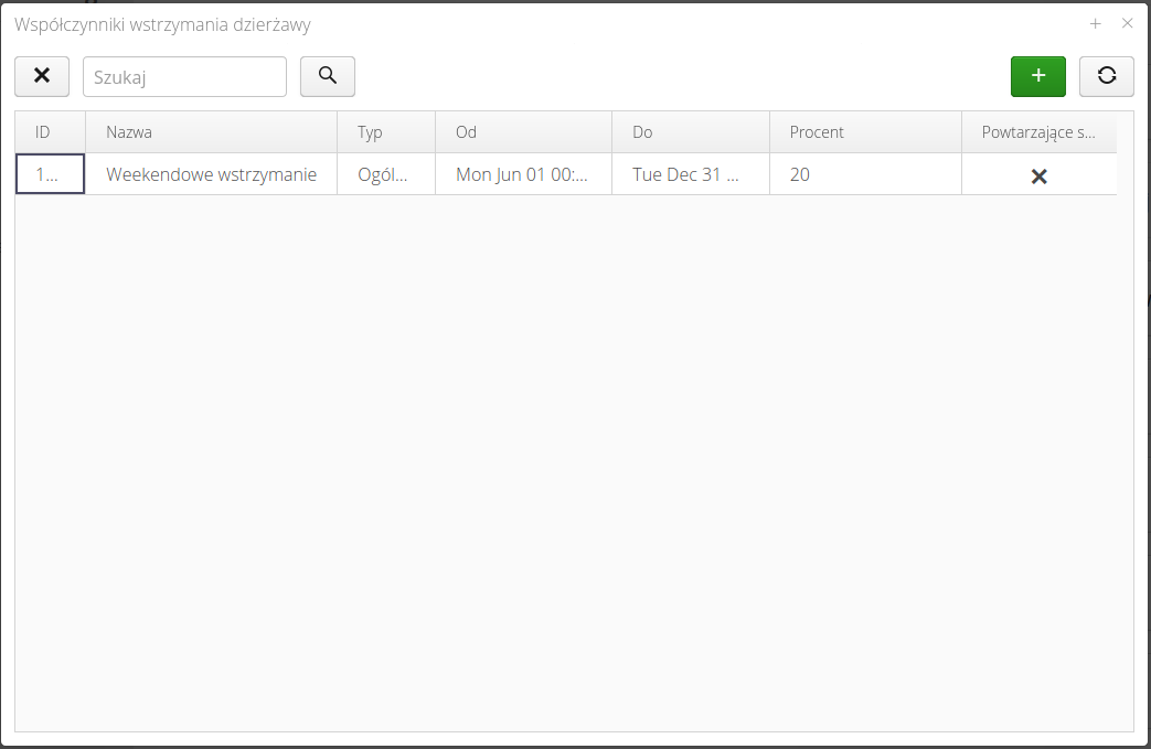
The creation/editing of a new lease hold is defined using the editor, where we specify the parameters.
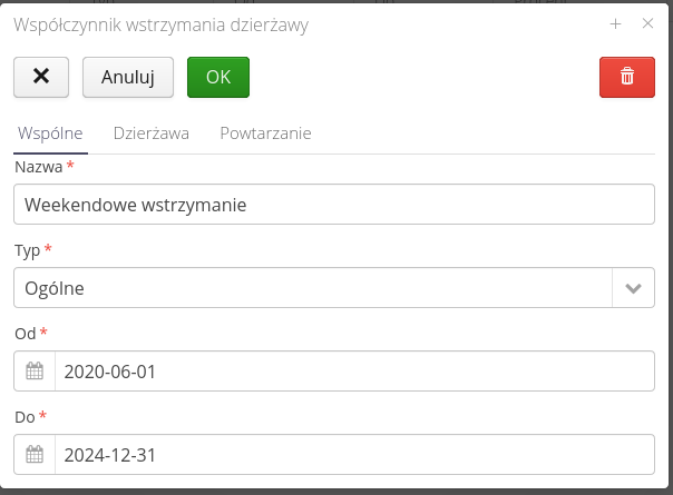
In the Common tab, you define the name, the type of hold (different handling for regular hold or minor device hold) and the duration of the hold.
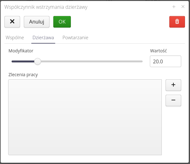
In the lease tab, we define percentage of the lease modification value, i.e. specifying a value of 0% means that no lease will be charged in a given period. Specifying a value of 50% means that half of the value that is required on the given days will be charged (broken down by day). In this tab we also define whether the withholding applies to all construction elements or only to selected ones, which can be specified using the list of these elements.
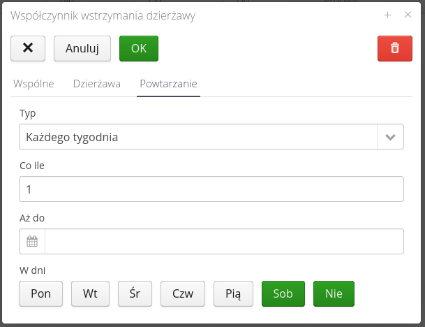
In the recurrence tab, we define whether a given hold is recurring and have the option to specify the type of recurrence, the period every which it will be calculated, the end date of the recurrence and the days of the week on which the recurrence will be active.
For example, you can define repetition:
-
Every week
-
With an interval of 2 - that is, every two weeks
-
With an end date, for example, at the end of the year (Dec. 31)
-
On weekdays Sat/nd.
This means that the system will repeat the defined hold every two weeks until the end of the year, but only if, after moving the interval, it turns out that these days are Saturday or Sunday (useful for repeating, for example, every certain number of days).
Configuration - maps
Definition interface of custom map primers. The definition allows you to upload to the system and select the map in map viewers.
| The configuration is available in systems that have their own map server configured, which replaces the publicly available OpenStreetMap type map server. Configuration of the server type is carried out during system deployment configuration by AMAGE Systems. |

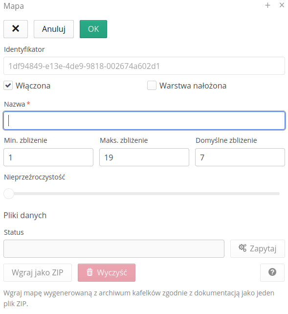
The procedure for adding maps requires specifying a map name and basic map information (minimum zoom/maximum and default). When the map is created, a unique identifier is assigned to the map, which will be used to upload the map’s tiled backing to the server.
The system also allows you to add a default map by selecting the Default button, which will automatically add a map based on Open Street Map (OSM) primers. The system will then create a local copy of OSM tiles to serve to users while speeding up transfers and minimizing communication with public OSM servers.
When defining your own maps, it is important to define the maximum/minimum map level and default zoom.
If we mark the map as a map overlaid on geographic maps, it will appear above the selected main layer. Using the "Opacity" slider, we can determine how transparent the layer is. 0% - fully transparent, 100% - completely masking.
| The construction of map data and its placement on the server is carried out during the deployment procedure. The source of maps can be DWG files or large raster/vector images. In any case, during implementation, such images are adapted to the way such data is delivered to browsers (tiles - tiles containing a slice of the view of the entire map/plan) |
| We encourage you to actively contribute to OpenStreetMap by editing areas that you are familiar with. This increases the accuracy, timeliness of this system. More at: Open Street Map |
Configuration - parameter templates
The system has the ability to define any parameters for types/resources in the system. Usually between devices/types, some of the parameters are repeatable, e.g. electrical parameters, environmental parameters, etc. To make it easier to give such parameters in a repeatable way, the system introduces something like parameter templates.
Parameter templates are user-definable groups of parameters that can be used when creating/defining new types of resources so as to facilitate and speed up these operations.
The list of parameter templates shows all templates available in the system.
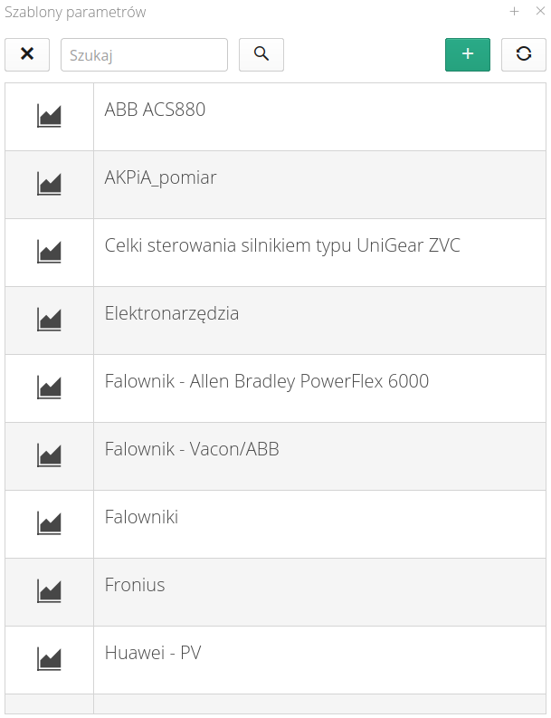
| Template selection when creating a new resource type is possible in the editor of the type. |
Adding/editing a new template is accomplished either by the (+) button or by selecting a template for editing.
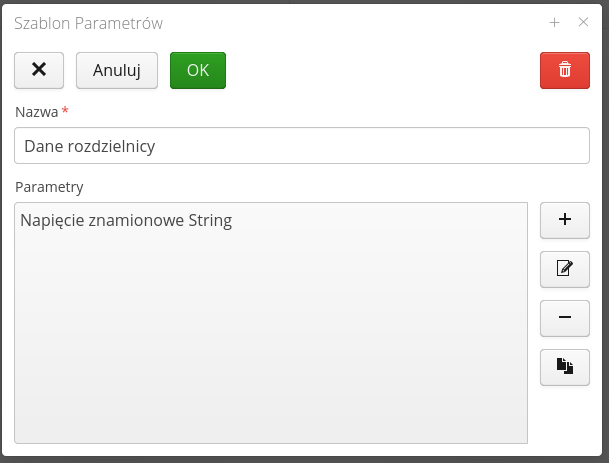
In the template editor, we define its name and specify the list of parameters that make up the parameter template. Using the dedicated Copy button, we can quickly copy parameters and edit them later in a simplified manner.
The definition of a single parameter allows you to specify its value and additional information.
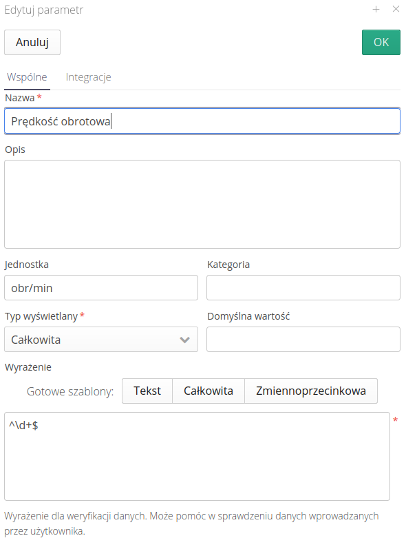
Available fields:
-
Name - Name of the parameter
-
Description - Additional textual description of the parameter.
-
Unit - Unit of measurement. Displayed for users.
-
Category - Category of the parameter. Parameters can be grouped into categories.
-
Default value - Default value of the parameter. When adding a new resource, it receives a parameter package. If there is a default value entered here, it will be copied to the resource (with the possibility to change it later).
-
Display type - the display type of the parameter. On it depends the available editor (e.g. text field, date field).
-
Expression - checking expression. At the bottom there are three buttons that predefine the checking expression for the most common data types. The expression is a regular expression (RegExp) with the help of which the system checks whether a parameter is of a certain format. This allows you to pre-validate fields during data entry.
| The Integrations section allows you to define data for integration systems or edge computing solutions. Refer to the parameter documentation for more information. |
| Regular expressions are a very powerful mechanism that allows you to define virtually any rules. For more information, see websites about this mechanism, e.g. www.regexpal.com |
Configuration - service event states
Interface for definition of service event states and definition of possible flows/changes between states of an event.

| The states of a service event correspond to the successive stages of an event. They can represent the simplest course, i.e. New, In Progress, Completed, or more complicated ones, corresponding to the actual circulation of the event taking into account, for example, the procedure of device acceptance, damage assessment, invoicing process, etc. |
To create or edit an event, select the (+) button at the top of the window or select the state you want to edit and then select the 'Edit' button.
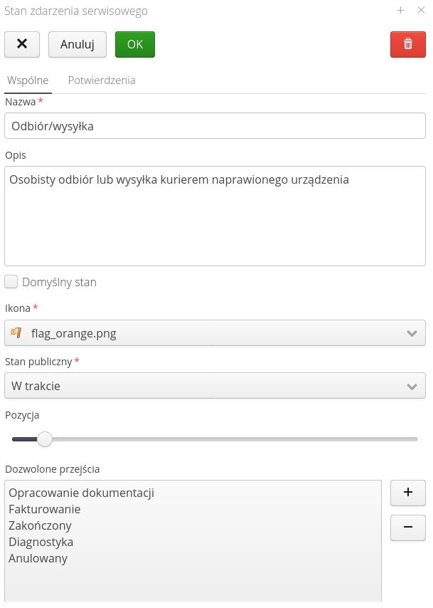
Only one service event state must have the "Default state" flag. This will be the state that is set first when the service event is created.
Public states determine the mappings of the list of service event states to the states visible in the Customer Portal.
| Usually in the service process there are many internal states that should not be signaled to the external customer, e.g. analysis, repair, invoicing. Instead, the system in the Customer Portal switches only three states: New, In Progress, Resolved. With this mapping, we determine how to present internal states in the Customer Portal |
The list of allowed transitions allows you to specify the possible flow between states. If it is filled, the system user will be able to move from a given state only to selected states from the list
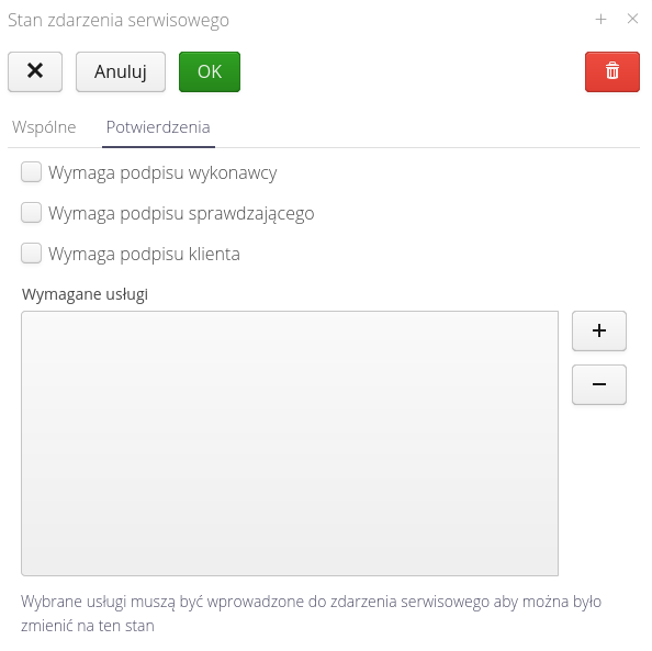
The flags of required confirmations are used when performing service work and entering data using mobile devices. The requirement to enter signatures of relevant people will result in showing dialogs with the need for signatures (or using signatures stored in the system - see the definition of users).
The list of required services allows you to specify what services must be entered into a service event in order for the system to allow you to move to that state. This allows you to determine which services (e.g. number of hours worked, trip amount, etc.) are to be entered into a service event before moving to the next step (service event state).
Colors of event states
The application allows you to define colors for individual service event states. These colors are used in various places in the application, e.g. in the list view of service events, in the detailed view of a service event, etc. In the 'Visual' tab there is an option that allows you to enable non-standard colors and define these colors
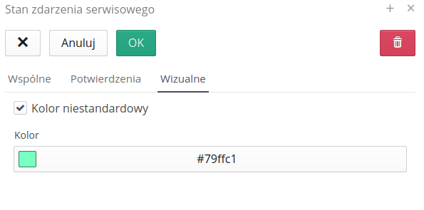
After saving data in this section, the colors defined for individual service event states will be visible in the views that include service events.
Permissions
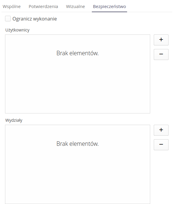
Using the Security tab, you can specify who has the right to change service event statuses. By enabling the appropriate flags, you can specify who has the right to change service event statuses. The Limit execution field allows you to specify that only selected people can change the service event status. Using the list of users or departments to which users are assigned, you can specify who has the right to change service event statuses. Only the indicated users or departments will be able to change service event statuses.
Configuration - service event states
Definition of service event types. Defining event type for easier event categorization.

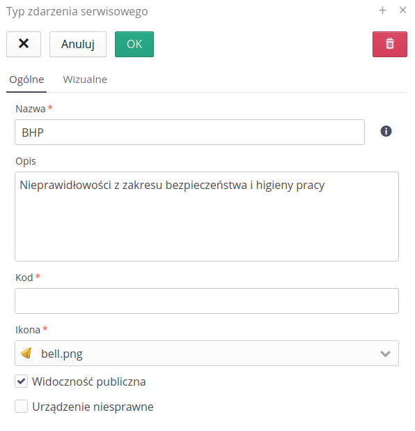
The editor allows you to define the following parameters:
-
Name - name of the event type
-
Icon - icon of the event type that will be displayed in the application
-
Code - event type code. Often used in integrations with external systems.
-
Description - description of the event type
Flags relevant to event type definition:
-
Public visibility - enabling this option displays this type of event in the Customer Portal. We allow you to select this type of notification to an external customer through the above-mentioned portal.
-
Device inoperative - activating this flag will result in equipment rental billing treating the activity time of a given service event (from the time it was reported to the time it was resolved) as time excluded from rental billing
Colors of service event types
The colors of service event types, available in the 'Visual' tab, allow you to define non-standard colors for particular types of service events. After enabling the custom color option, you can select a color from the color palette or manually enter RGB/HSV values in the text fields.
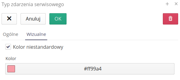
The color selection control allows you to select a color from the RGB/HSV color palette and from predefined colors in the Swatches tab.

After saving the changes, the color will be displayed in the list of service event types and in the service event detail view.

Permissions
Using the Security tab, you can specify who has the right to create service events of a given type. By enabling the appropriate flags, you can specify who has the right to create service event types. The Limit execution field allows you to specify that only selected people can create a given type of service event. Using the list of users or departments to which users are assigned, you can specify who has the right to change service event types.
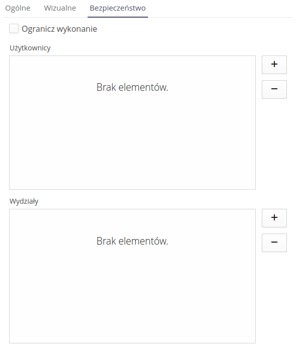
Configuration - services
Services are a cost component of service events, service protocols or inspection work performed. Using it, additional information can be written to the aforementioned objects to estimate the cost of executing a given order. With the help of services, you can define costs that are not costs of items from the warehouse (handled by warehouse outgoings), but also that are part of the load of a given request/protocol/inspection. In the dictionaries we define such things as:
-
Hours worked
-
External invoices (service providers, subcontractors)
-
Warehouse documents from external systems (ERP)
| Service values can be synchronized with external systems such as the Finance and Accounting system to retrieve invoice costs, or the warehouse system in ERP software, or working time from Time & Attendance systems. |
The list of available service types allows you to view all the services defined in the system and edit/create new ones.

Creating a new type of service allows you to enter all the basic data about that service
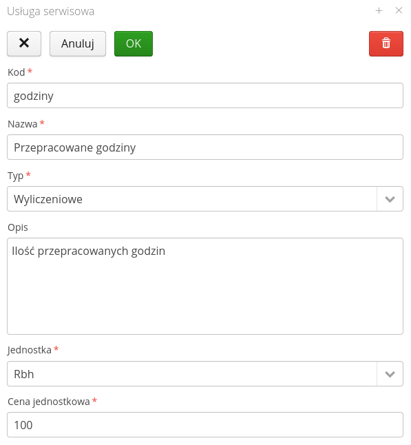
Possible data entry:
-
Code - code for the type of service. Used, for example, when exchanging data with external systems. Usually it is a code value that is easy to enter/transfer between information systems
-
Name - the name of the service. User-friendly name.
-
Type - type of service. The service can be enumerative i.e. indicating an exact numerical value (cost, hours, value, etc.) or descriptive i.e. defined only by a description without a specific numerical value
-
Description - description of the type of service. Data for the user.
-
Unit - unit of measurement
-
Unit price - unit price of one unit of a given service, e.g. price per kilometer of travel, value of labor hour, etc.
Configuration - warehouses
Warehouses are the central clearinghouse of warehouse management. Each warehouse can divide into multiple storage locations (locations where items are stored in the warehouse). Definition of warehouses is done manually using the interface below or automatically when importing project/contract structures or integrating with external ERP systems.
After entering the warehouse configuration, the user is presented with a list of all defined warehouses and their basic properties.

Adding/editing a warehouse is possible by selecting the (+) button or by selecting a specific warehouse.
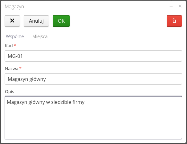
Available parameters for the warehouse:
-
Code - the code name of the warehouse. Often used as a code for data exchange between the AMAGE system and external information systems.
-
Name - the name of the warehouse, user-friendly.
-
Description - additional description of the warehouse, e.g. its location and purpose.
-
Storage locations - a list of storage locations that are associated with the warehouse. The list can be edited and modified.
| The system requires at least one storage location for the warehouse to be able to perform warehouse operations. |
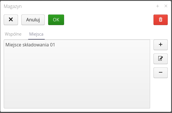
A storage location is defined as descriptive information of the location. You can also assign a billing account and a location to a storage location, which allows you to display the storage location on a map and send this information to users and suppliers (where to deliver materials).
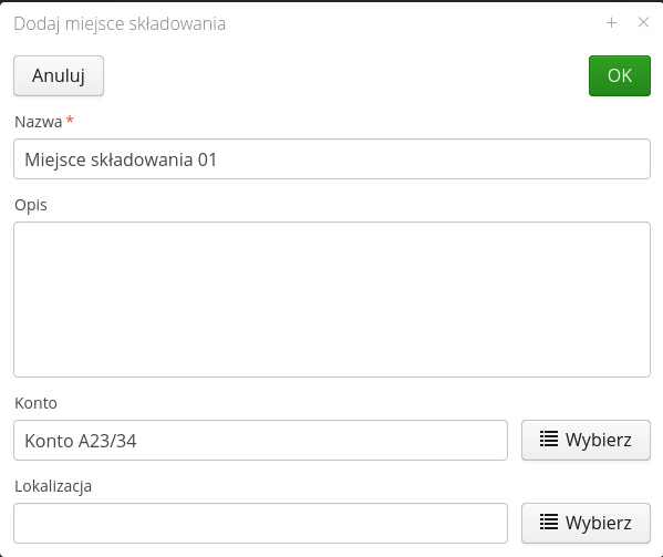
The details of the storage site are:
-
Name - the name of the place, user-friendly.
-
Description - description of the storage location. User information.
-
Account - an account that is associated with a particular warehouse/storage location.
-
Location - location of storage site
Parameters - allow you to define what parameters should be displayed directly in the view of a given warehouse in the form of additional columns with data.
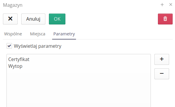
| To use this feature, it must be enabled in the system configuration options. |

Configuration - Units of measurement
The system allows you to define units of measurement and their representation in the system. To go to the definition of units, select the 'Unit of measurement' option in the dictionary configuration.

After selecting this option, a window with predefined units in the system appears. During the first startup, the system defines the units in the system and determines their parameters. We can change these parameters and/or define new units of measurement.
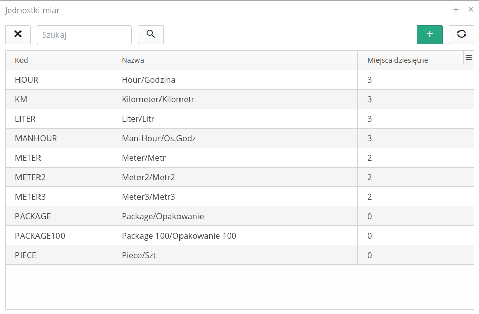
The unit of measurement has the following parameters:
-
Code - code allows you to use this code for operations such as data import/export.
-
Name - The name of the entity that makes it easier to understand its meaning
-
Abbreviation - an abbreviation that will appear in the system, e.g. in column headings or field descriptions, e.g. m, kg, pcs.
-
Decimal places - The number of decimal places to represent in the system for a given unit. Depending on the arrangements or industry specializations, these data may be defined in different ways. Pieces are counted as integers by default. Meters with two decimal places. Etc. The system allows you to change or specify this accuracy.
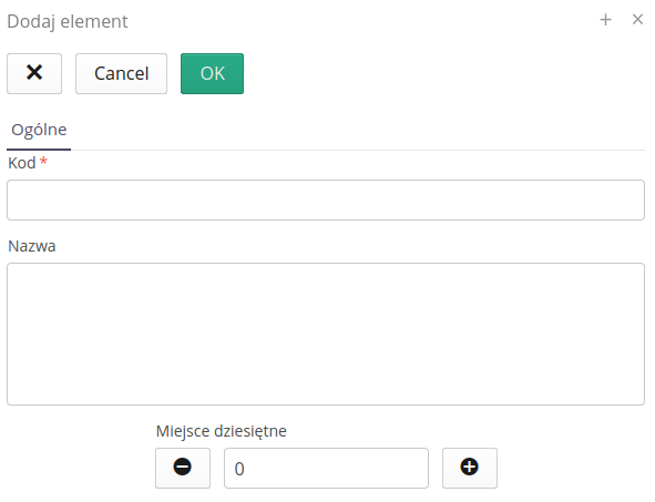
| The only unit that cannot be changed is `Piece' (PIECE). This is because it is the default unit that is used by the system if no unit is defined for a given type of element in the system. |