Configuration of hardware components
Introduction
This document describes the configuration of selected hardware components for proper cooperation with the AMAGE application.
Label printers
Label printers, due to their use for printing on any type of media with very different dimensions, require appropriate calibration and internal settings in accordance with the additional equipment (e.g. cutters) and own parameters (e.g. heating of printheads), which are completely different than standard office printers.
| All thermal transfer (label) printers are sensitive to the surface of the material. Do not touch (fat) labels with your hands before printing. Otherwise, thermal dye transfer will fail and the label will be unevenly marked. |
CAB printers - PARTEX, HELLERMAN & TYTON
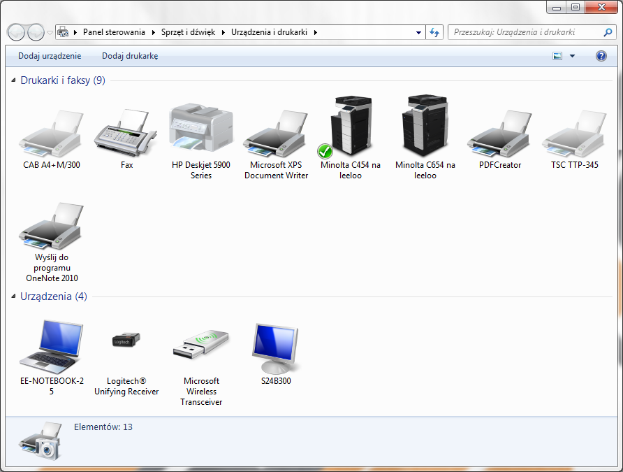
The installation of CAB printers or CAB printers sold by label manufacturers, i.e. PARTEX and HELLERMAN&TYTON in Windows 7/8.x/10 systems, takes place automatically after connecting the printer to the computer with a USB cable. In order for the drivers to be detected, you must have an internet connection and local computer administrator rights. After installation, the printer appears on the control panel under "Devices and Printers" as shown in Figure 1.
| If you do not have an Internet connection, you can use the installation discs supplied with the printer, which contain drivers for popular operating systems. |
In order to prepare the printer for proper operation in the system, you must define the sizes of labels accepted by the printer. In this case, it is possible to print from the AMAGE application directly to the label printer, omitting the paper size and printer selection windows, completely automating the printouts.
Label size definition
In order to define the types of labels used, select the label printer in the "Devices and printers" panel and select "Printer properties" from the context menu (available under the right mouse button). The window shown in Figure 2 will appear.
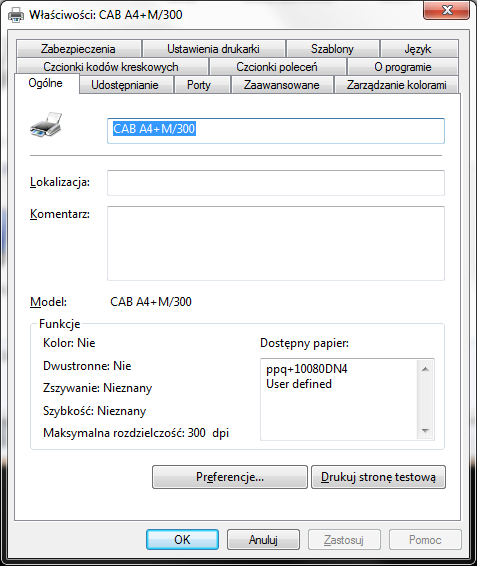
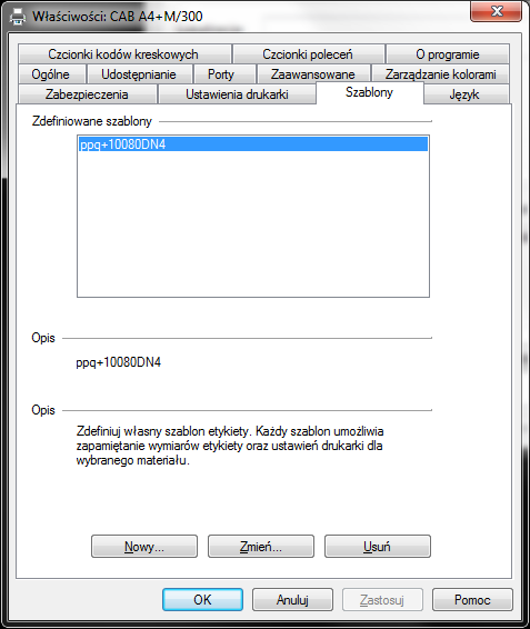
Printer settings allow you to define general printer data available for applications using this print medium. In order to define new label formats, go to the "Templates" tab, as shown in Fig. 3. In this window, it is possible to define/change the available label templates.
To define a new label template, select the "New…" option. After selecting a new template definition window appears - Fig. 4. The window is used to define the template name, label size, print speed and non-printable areas.
| For the AMAGE application, the name of the template is not important. During label printing automation, the application searches for a label template with the same size as the selected label in the application itself. After adjusting the dimensions, such a template is selected for printing. |
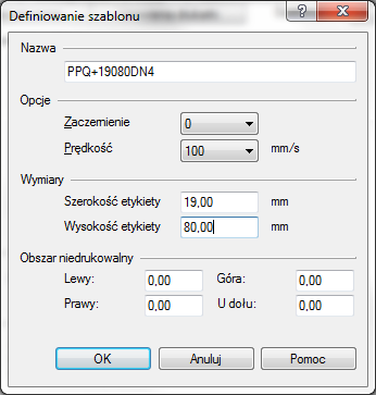
Figure 4 shows an exemplary definition of labels for PARTEX PPQ+19080DN4 labels, i.e. labels with a label width of 19mm and a height of 80mm. Margins should always be set to 0mm.
| You must define all the templates for the labels you want to work with. If no appropriate template is defined, the application will select the default label size defined in the global printer options. |
| If the printer skips a single label from the tape during printing - for labels with a specific length, such as Partex PPQ labels, reduce the label height by approx. This will allow the label to shift less during printing and allow the printer to detect the new label start mark (vertical gap in the continuous label material). |
Additional properties
If you have additional printer accessories (cutters, etc.), you can define the behavior of the printer in the advanced settings by selecting the "Advanced" tab, as shown in Figure 5. To go to the default printing settings of CAB printers, select the "Default printing settings" button.
After selecting the button, an additional window appears with all available printer options. Changing these settings changes the default settings when printing from any application on the system.
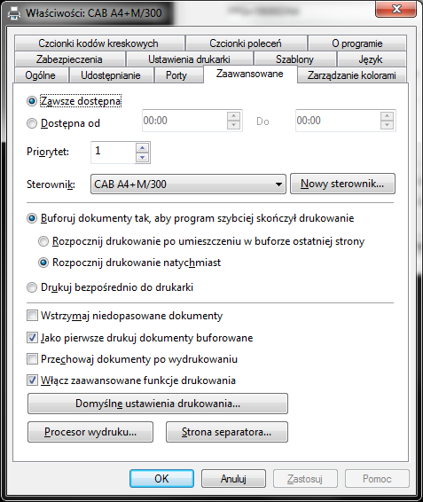
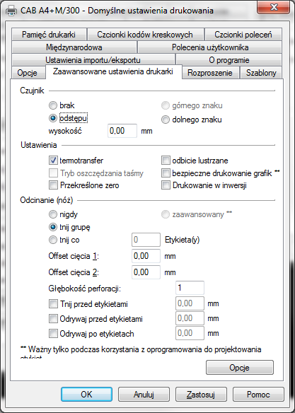
In the case of additional elements, the "Advanced printer settings" tab - fig. 6 - is worth attention, where you can define the specialized behavior of the printer. Such options are, for example:
-
Label sensor type setting - When using a cutter, select "none", i.e. continuous label material.
-
Cutting - where you can set the way of cutting after each label or after a printout group (set of labels) and other specialized steps to adapt the cutting to the available material.
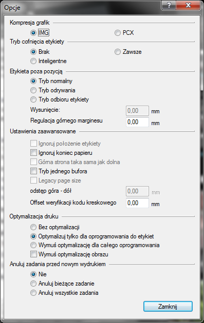
In addition, after selecting the "Options" button, advanced printer settings appear as shown in Figure 7.
Noteworthy options are:
-
Label withdrawal mode - after printing, the label is sent to be torn off, and then when printing is resumed, the label returns (retracts) to a position that allows it to be correctly printed from the beginning of the place of printing
-
Label out of position – allows you to eject the label strip after printing in accordance with the definition of additional settings. label after printing will be pulled out so that it can be easily torn off.
Zebra printers e.g. GK420t
Zebra printers are installed automatically by the Windows 7+ operating system. Otherwise, or if there is no network, download the appropriate drivers from https://www.zebra.com/gb/en/support-downloads.html beforehand. After the printer is installed, it appears in the Printers and Other Devices panel (Figure 1). In the properties of the printout (printing preferences), set the basic type of labels on the printout. In this window you can define text density, non-printable areas and print speed.
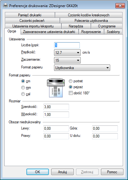
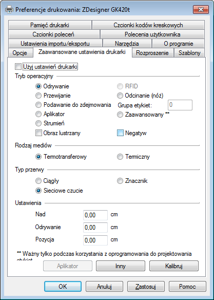
Advanced printer settings allow you to set the way of printing, operating mode (use of cutters, etc.). All information can be found in the "advanced printer settings" - Figure 9.
Label size definition
To enable correct printing using the automatic method of printing, you must define templates corresponding to your label sizes in the configuration of the Zebra printer. To do this, in the printing preferences, go to the "Templates" tab - Figure 11 and select to add/edit a label template.
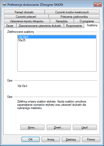
To support all the label sizes you use, you must define the same number of different label formats.
| For the AMAGE application, the name of the template is not important. During label printing automation, the application searches for a label template with the same size as the selected label in the application itself. After adjusting the dimensions, such a template is selected for printing. |
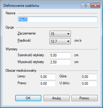
The view of the template definition is shown in Fig. 11. Specify the size of the label according to the available labels. In the case of combined labels, e.g. three 10x10 mm labels placed in the same row on the tape, the total size of the label should be defined, not a single cell.
| You must define all the templates for the labels you want to work with. If no appropriate template is defined, the application will select the default label size defined in the global printer options. |
TSC printers, e.g. TPP-345
The TSC (Toshiba) printer installs automatically when connected to the computer. In the absence of an Internet connection or problems with automatic installation, download drivers for the appropriate printer from the manufacturer’s website: http://www.tscprinters.com/cms/theme/index-39.html
After installation, the printer appears in the list of printers and other devices (Figure 1). To enable printing on defined labels, go to the printer’s printing preferences by selecting these options from the printer’s context menu (right mouse button).
After selecting the option, the printing preferences window will appear as shown in Figure 12.
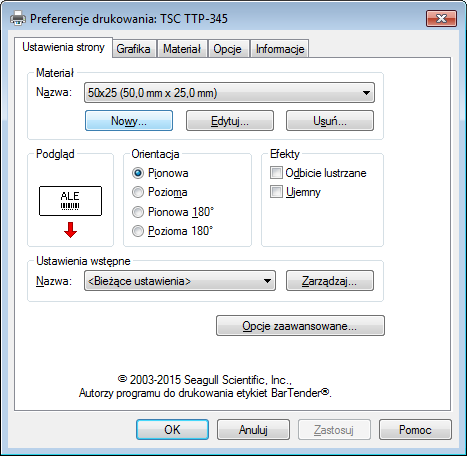
In the default printing preferences, you can specify the printing orientation, effects, and additional printing operations.
Label size definition
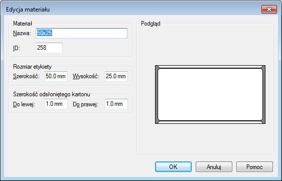
In order to define the label sizes used, you need to define them using the Edit/New buttons in the "Material" section. Definition of a new label consists in entering information about the width and height of the label along with information about the available margins.
| For the AMAGE application, the name of the template is not important. During label printing automation, the application searches for a label template with the same size as the selected label in the application itself. After adjusting the dimensions, such a template is selected for printing. |
| You must define all the templates for the labels you want to work with. If no appropriate template is defined, the application will select the default label size defined in the global printer options. |
Label printing - Linux system
Installing printer drivers is outside of these tutorials. Refer to the readme files or documentation on manufacturers' websites. The correctness of label printing on CAB and TSC printers (as above) for the Linux system was checked by connecting the devices both via the USB interface and via the network interface.
The installation was standard and can usually be divided into two stages:
-
Installation of PPD definitions for a given manufacturer’s printers - usually through installation scripts in archives
-
Adding a printer - through the usual interface of a given environment (such as Gnome)
Depending on the printer, the printout needs to be set appropriately in terms of position, settings or rotation. After the first setting, usually further printing works automatically.
An example printout using a CAB printer looks like this:
Open the labels prepared in AMAGE for printing
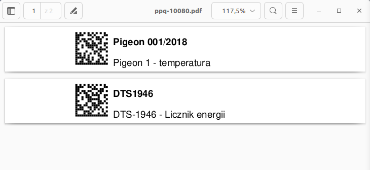
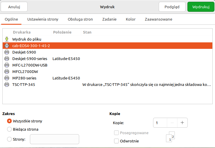
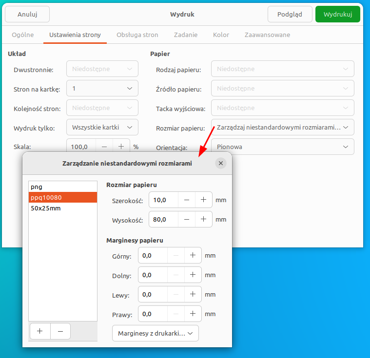
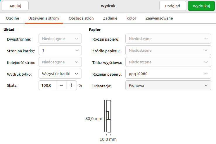
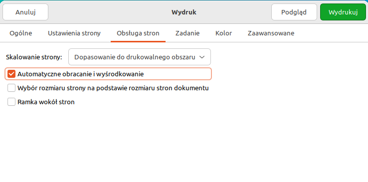
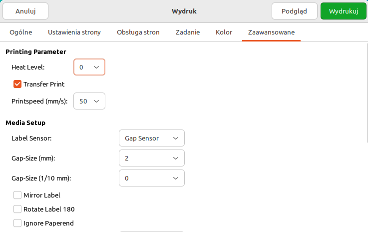
The printout is printed correctly. Done :)
Mobile terminals
This chapter presents information about mobile terminals, how to configure them, and about hardware and software settings that facilitate their use.
CASIO DT-X8/DT-X200 terminal
The CASIO DT-X8 terminal and its successor DT-X200 are devices with increased environmental resistance and at the same time compact.
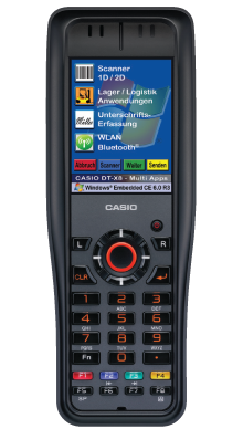
The terminal is shown in Fig. 14. The terminal is equipped with a numeric keypad as well as function and special keys:
-
Bar codes are read using the keys marked with an orange border. There are: one centrally on the keyboard and two on the sides of the housing.
-
The options are approved by pressing the ENTER key (arrow)
-
Cancel selection with CLR key
-
Navigation using the cursor keys located around the barcode reading button
-
Color coded function keys F1-F4.
-
Changing the F8 input method (numbers/lowercase/uppercase letters)
-
The screen is touch.
-
Docking stations allow you to charge/communicate your device with the outside world
-
Basic station - for USB connection and power supply
-
USB desk station - a station that facilitates the storage of a terminal with a USB output to a computer
-
ETH desk station - a station that facilitates the storage of a terminal with an ETHERNET output to the network infrastructure
-
All software options of the device are located in the Control Panel, which can be accessed through the start menu and through the shortcut in the file explorer.
Control Panel
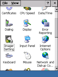
The control panel contains all possible applets that allow you to configure the device. They are accessed by selecting a specific icon from the control panel (Fig. 15).
Setting the date and time
After entering the "Date/==Time" panel, a window is presented as shown in Fig. 16. In the window, you can set the current date and time.
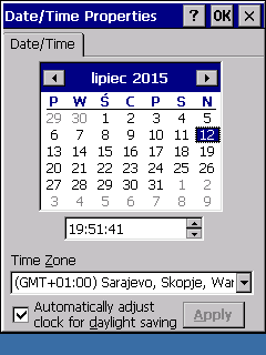
| A very important setting is the time zone. If the zone is set incorrectly, the time in the terminal will be presented to the user correctly, but the data sent to external systems will be sent with a different time zone than in which the user is currently located. This will move time! |
Configuration of the 1D/2D code reader
After entering the "Imager Setting" option (Fig. 17), we are redirected to the application configuring the 1D/2D reader in the terminal. All available functions of the reader appear in the tabs.
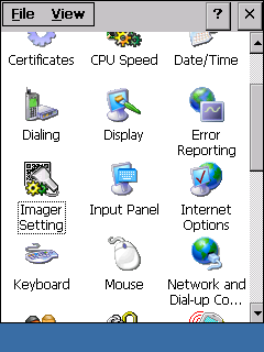
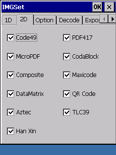
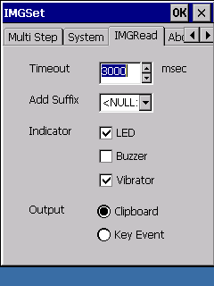
The most important settings are read 1D/2D codes (fig. 18) and signaling the read code to the user (fig. 19).
In the case of the AMAGE application, the basic identification code is the 2D DataMatrix code, and it must be marked as supported by the reader. Otherwise, the reader will not read such a code.
USB communication with PC
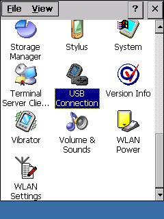
Access to the definition of wired communication is carried out through the "USB Connection" panel (Fig. 20). USB wired communication to the computer uses two methods to access these resources:
-
ActiveSync/LMWIN – valid for Windows XP family systems
-
Windows Mobile Device Center (WMDC) – valid for Windows 7/8/+ family systems
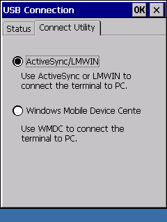
| If an option incompatible with the system to which the terminal is connected is selected, the connection will be impossible. The terminal and the computer can signal this in different ways, even signaling an attempt to connect and then breaking it. You should always check the current way of communication. |
Power Settings
The user can set the power saving scheme (Fig. 22) both in the case of mains power ("AC Line") and battery power ("Battery Power"). After entering the power management panel, the user can see the battery status (charge level) and set power schemes in the "Schemes" tab.
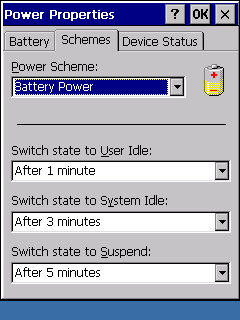
The user can set the times:
-
followed by a transition to the user-level standby time ("User Idle")
-
followed by transition to system level standby time ("System Idle")
-
"Suspend"
Sound setup
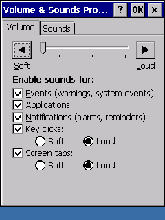
In the sound configuration, you can set the volume level of the played sounds and which sounds will be signaled to the user (Fig. 23).
WiFi wireless interface
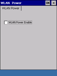
The configuration of the wireless network is carried out through the panels "WLAN Power" (Fig. 22) and "WLAN Settings" (Fig. 25). The "WLAN Power" option allows you to enable the Wi-Fi network interface. To do this, enable "WLAN Power Enable" in this control panel. If you want to reduce energy consumption and you do not need a network interface, you can disable this interface.
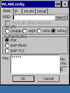
Detailed settings for access to the Wi-Fi network are configured using the "WLAN Settings" applet. In it, there is an opportunity to select the network identifier SSID, encryption and passwords. Applying changes requires restarting the device.
Regional Settings
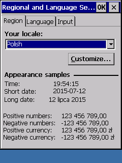
If you want to display personalized regional settings, you can do it in the "Regional and Language Settings" applet (fig. 24). The choice of location determines how e.g. hours, numbers, etc. are presented.
Label engraving
In order to engrave labels generated by the AMAGE software, the following work must be done both in the AMAGE software and in the software for operating the burner.
-
Generate labels for group engraving (separate label types). Label sizes are 17mm*50mm, 17mm*65mm, 40mm*100mm, 40mm*120mm, 40mm*150mm or others.
-
The labels contain a 2D code, text information about the field and a red guide frame for engraving.
-
After generating the labels, save them in PDF format.
-
Go to the laser cutter software (Corel Draw) and import (Menu File→Import) the labels. Select to import all pages and replace fonts if any.
-
Arrange the labels on one side as required and start the engraving procedure.
tablets
Emdoor EM-I16H tablet
10" tablet with Windows 10 (Home/Pro) and 2D code scanners and integrated RFID HF reader.
-
The 2D code scanner is launched with the "F" button available on the top surface of the device
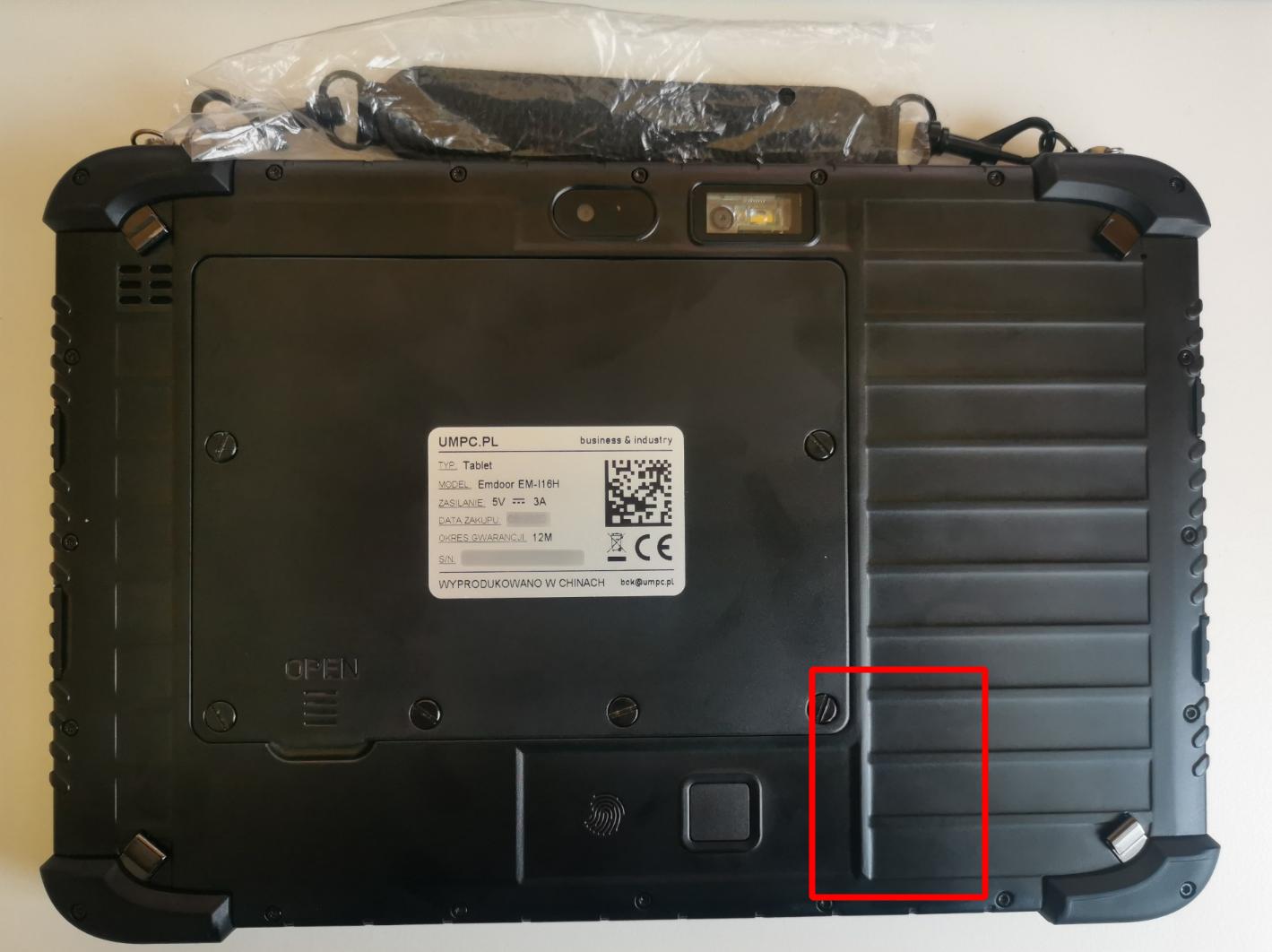
-
The RFID scanner is located on the back cover of the tablet in the place marked in the figure below
Samsung Galaxy Active 5 tablet or other Android
Android devices.
Keyboard
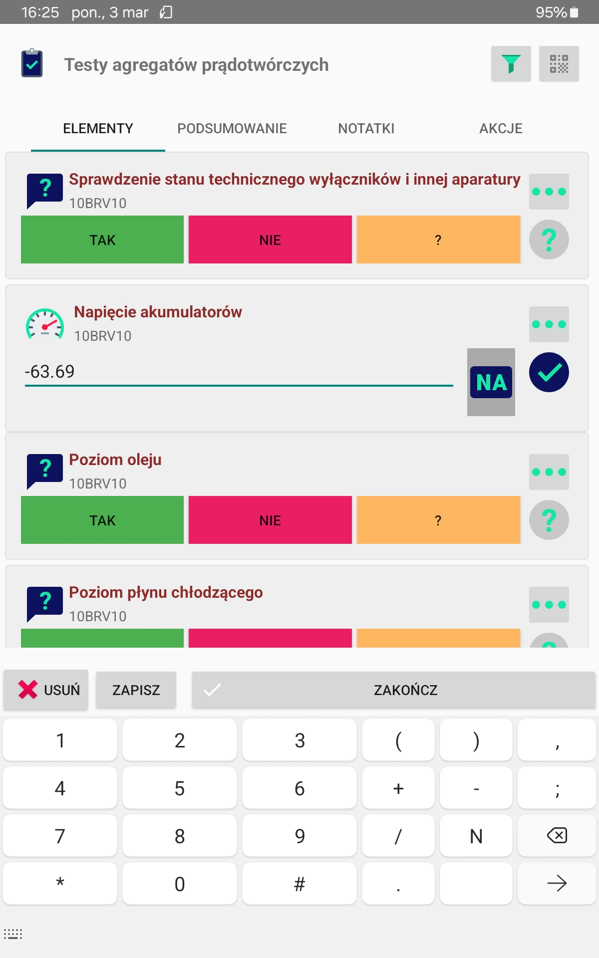
Sometimes, when using an application on a specific device, we may notice problems with using the virtual keyboard. Device manufacturers often provide their own design virtual keyboards, which may have some inconveniences when using the application. One of them is entering numbers, e.g. in maintenance systems. When entering a number, we need to have quick access to the minus sign, dot/decimal point. Sometimes these buttons are only available after selecting an additional action on the keyboard, e.g. changing the appearance. Therefore, below we provide two proven virtual keyboards that can be installed and used on a given device.
An example of such behavior can be found in Samsung Galaxy Active 5 devices. Tablet 8" with Android 13+ and integrated RFID HF reader. The default virtual keyboard has the minus/comma button hidden by default and this causes additional problems with data entry. You have to click the keyboard several times.
We can install another type of virtual keyboard (application) and change the appearance to suit our requirements. We have tested the following virtual keyboards:
-
Microsoft SwiftKey
-
Google Gboard
These applications are available in the standard Google Play stores. We can install them:
Google GBoard App

Microsoft SwiftKey App
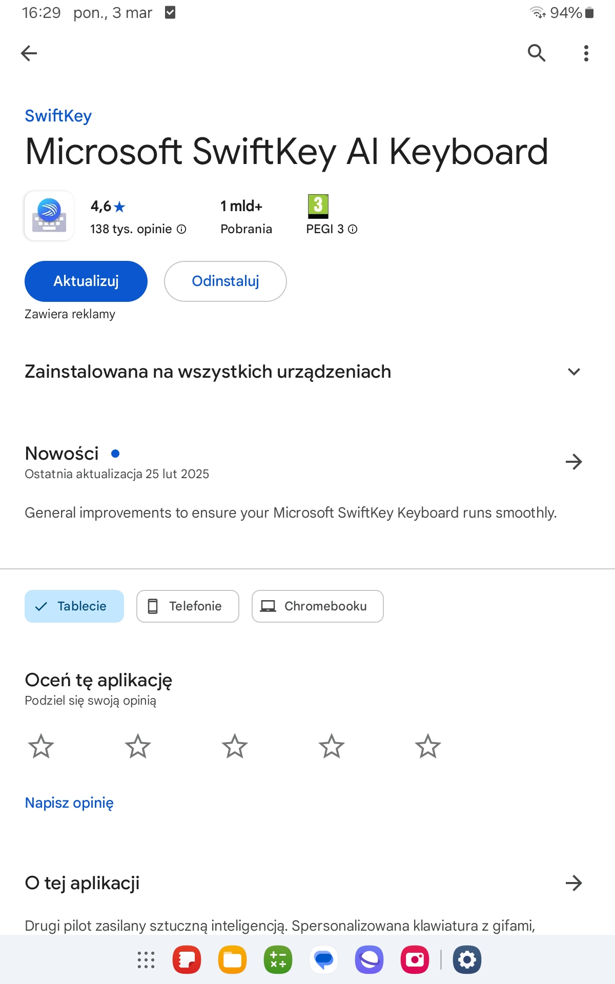
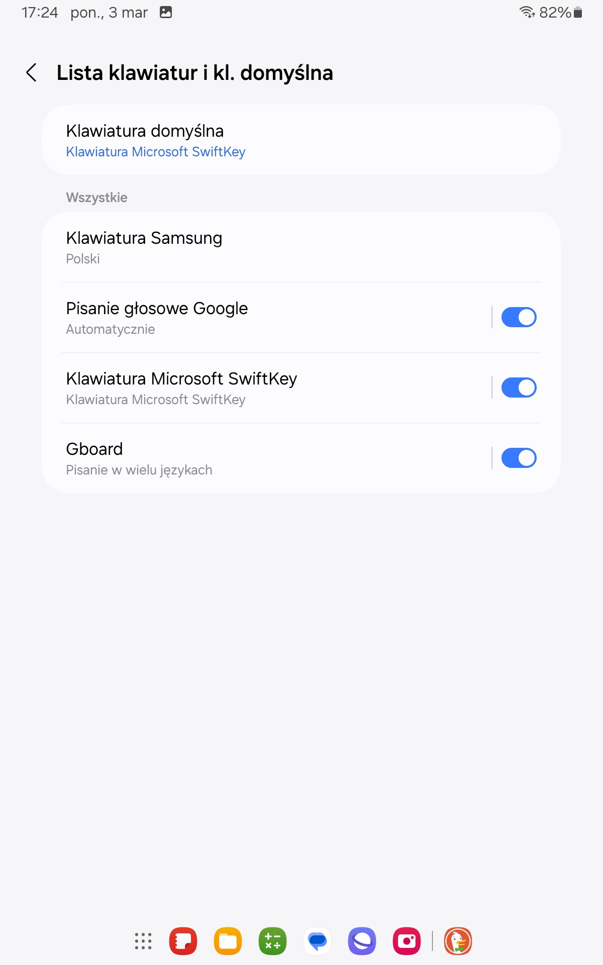
After installing the keyboard, go to the device configuration, select/find the section regarding keyboards and activate the availability of the above-mentioned installed keyboards for the user. We activate their availability, confirm the message regarding the potential risk. We can select the default keyboard on the same screen and change it to the preferred one.
Once activated, keyboards become available in the virtual keyboard view. You can use the above-mentioned default keyboard function or select the keyboard while typing.
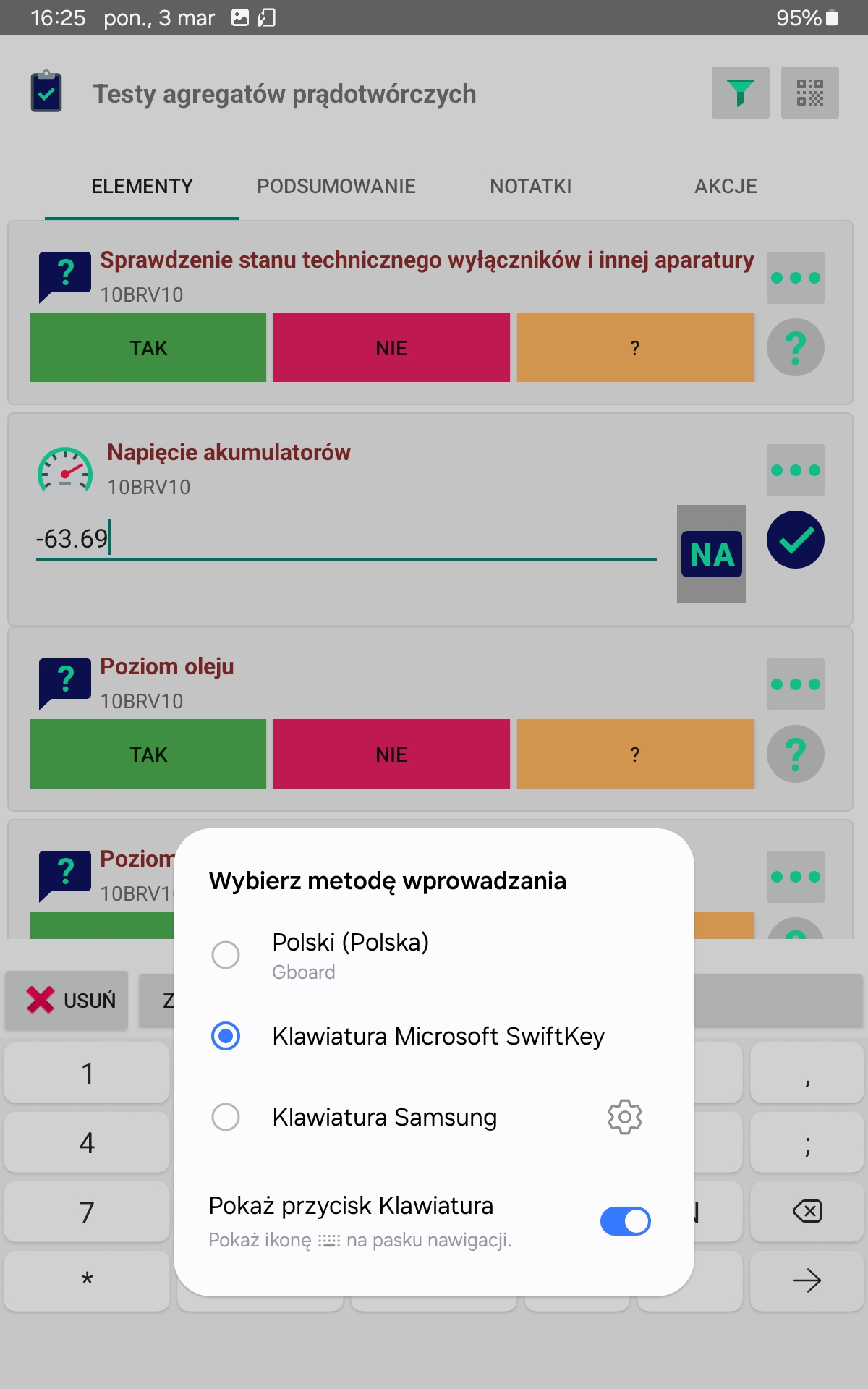
For example, performing a round using these keyboards directly shows a pin pad with numbers surrounded by additional functions that facilitate data entry (minus sign, comma, etc.)
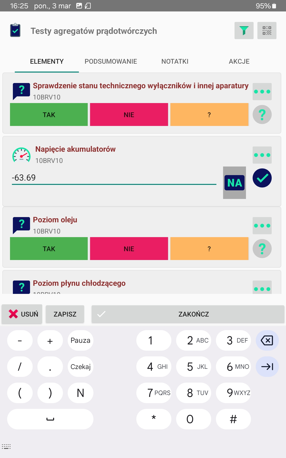
The Google Gboard keyboard has similar features with a different interface design but also has all the required buttons.
Tags Beacon Bluetooth
Active tags act as transmitters of specific information. They are equipped with a battery power supply and, according to the established configuration, transmit information. These are usually device identifiers, allowing the detection of the device in a specific area. Additionally, some tags allow the transmission of information such as battery status, temperature, and information from additional sensors such as shock sensors or inclinometers.
In the AMAGE system, these elements are usually used as intelligent location identifiers. In the inspection round system, this allows for filtering visible elements in the system or marking the presence of an employee in a given location.
Tags Mikrotik TG-BT-OUT
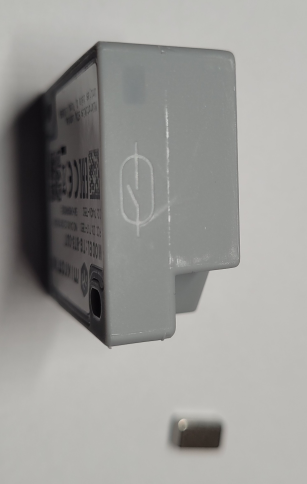
Mikrotik active tags require initial activation and then configuration. To activate the tag, you must turn it on by bringing a magnet close to the appropriate place on the housing. The application is signaled by a flashing diode located next to the activation point. After the flashing stops, the tag is ready for configuration.
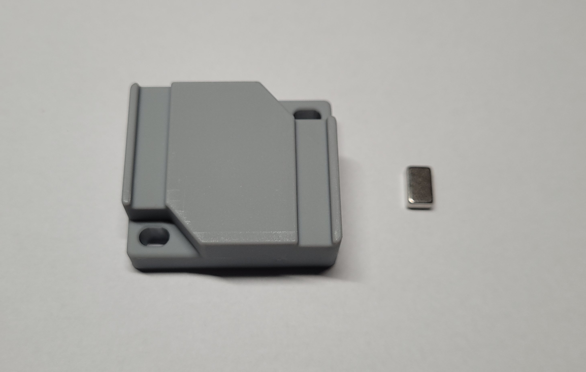
The location of the reed switch and LED diode is on the tag housing.
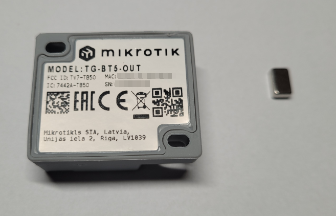
Another view of the tag. The code on the label makes it easy to add the tag to the management application.
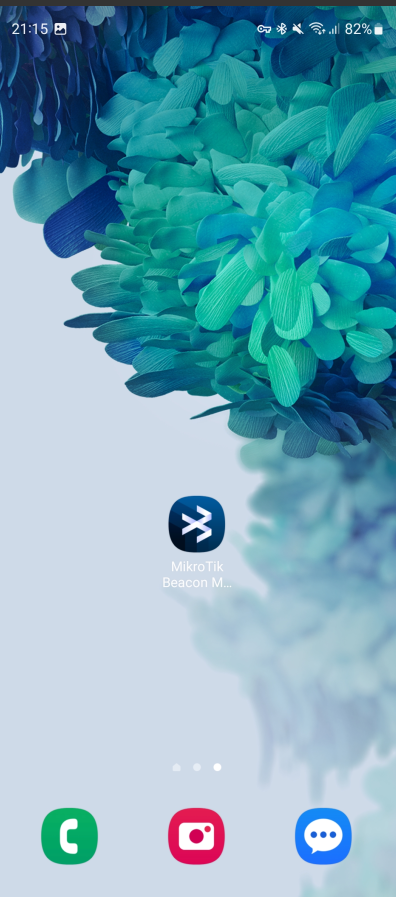
The tag is configured using the Mikrotik Beacon Manager app available in the Google Play store. It should be installed on any Android device with a Bluetooth interface.

After installation, we run the application.
The default view is to display all saved and newly detected tags in the system.
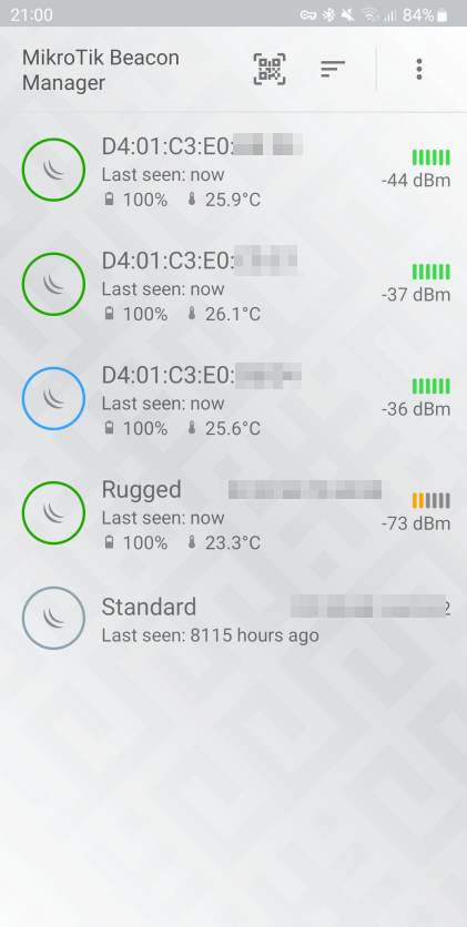
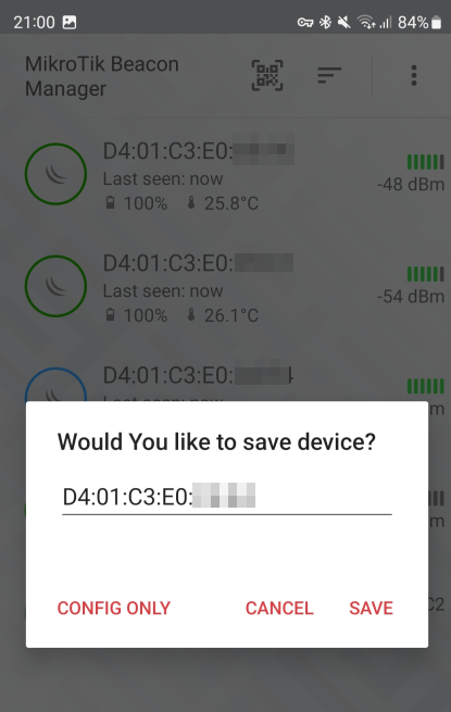
We select the tag that was detected and matches the MAC identifier recorded on the label. We save the tag in the local list. This will allow us to proceed to the device configuration.
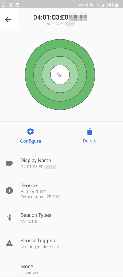
The detailed view displays basic information, estimated range to the tag and its signal strength. From here we can go to the device configuration. Additional information about the tag is also displayed here.
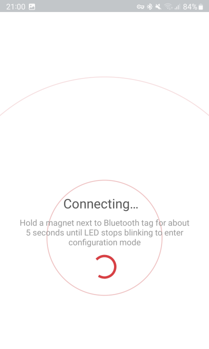
We choose to go to configuration. The configuration activation window is displayed. You should put the magnet to the appropriate place on the tag housing during the search or just before. You should experimentally choose the right moment.
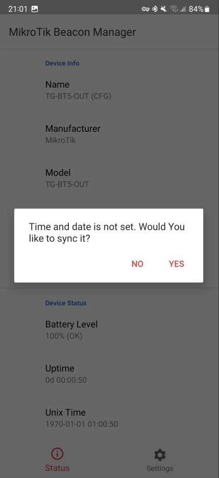
If the configuration is activated correctly, the window changes to the view of reading configuration parameters from the tag. You should wait until the reading is complete.

By default, for new tags, the date and time of this tag are proposed to be set. You must confirm the settings.
Usually, the tag configuration is set according to the adopted principles j/n. The user can change the configuration options at their own risk. The tag operating time for the selected configuration options should be taken into account. Setting an access password allows you to protect the tag from unauthorized editing.
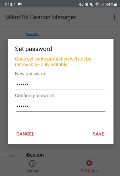
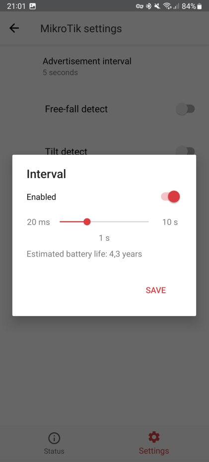
Then we modify the data sent by the device. In the AMAGE system we use the Mikrotik format (it also sends battery status and temperature) and change the reporting time to 1 second.
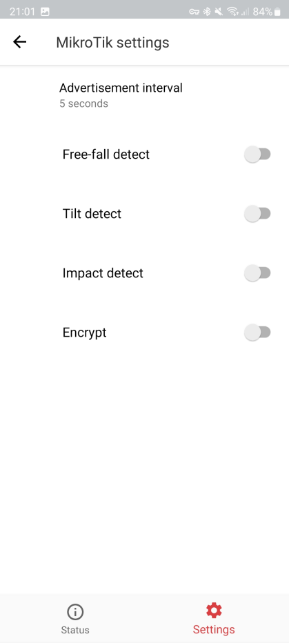
We change the reporting time to 1 second and save the settings.
Additional tag settings allow you to change the transmission power and enable additional tag functions. In AMAGE, they are not used for basic identification.
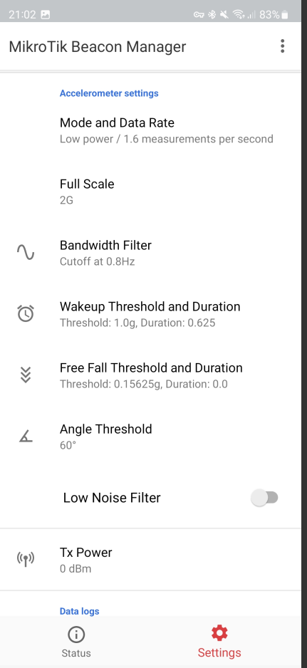
Changing the transmission power is a possible option to change. This allows you to change the tag’s visibility range based on the radiated power.
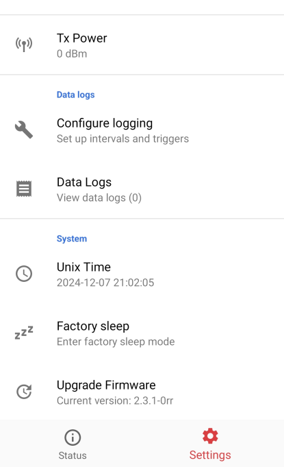
| The target transmission power and data transfer time settings should be set according to the purpose of the tag, its mounting method, environment (metallic environment) or the transmission time adapted to the data usage speed. |
Exiting the configuration saves the data and goes to the data preview.
