AMAGE PVD
Principle of operation
PVD może działać jako aplikacja terminalowa, jednak głównym założeniem jest praca ciągła, w charakterze usługi systemowej. Aplikacja ładuje i rejestruje moduły wtyczek wejściowych oraz wyjściowych. Kiedy wtyczka wejściowa generuje wiadomość, przekazuje ją do rdzenia aplikacji, a ta rozsyła ją do poszczególnych wtyczek wyjściowych. Aplikacja uruchamiana jest zarówno na urządzeniach embedded, jak i na komputerach klasy serwerowej. Może pracować w systemie Linux oraz Windows.
Wtyczki wejściowe i wyjściowe
Dopuszczalne są różne implementacje wtyczek wejściowych i wyjściowych. Wtyczka wejściowa odpowiada nie tylko za zebranie danych, ale też za utworzenie zalążka wiadomości w postaci mapowań UUID celu (standardowo ustawienie parametru zasobu w systemie Amage) na zebrane wartości. Następnie wtyczka przekazuje tak utworzoną wiadomość do rdzenia aplikacji PVD, który zajmuje się dalszym jej przetwarzaniem. Wtyczka wyjściowa odpowiada za obsługę wiadomości. Standardowo dostępną wtyczką wyjściową jest moduł odpowiadający za przekazywanie danych do sparowanego serwera Amage Software Suite.
Requirements
Jedynym bezwzględnym wymaganiem PVD jest dostępność środowiska uruchomieniowego Java w wersji 21 lub nowszej oraz ilość pamięci pozwalająca na buforowanie danych w przypadku problemów ze swobodnym przekazywaniem wiadomości wtyczkom wyjściowym - zalecane jest minimum 512 MB RAM.
Installation and configuration of applications
Instalacja aplikacji polega na rozpakowaniu archiwum pvd-all.zip w wybranej lokalizacji. W następnej kolejności należy skonfigurować aplikację oraz jej moduły, co opisane zostało w tym rozdziale. Pliki konfiguracyjne znajdują się w katalogu configs i podkatalogach, wszystkie pliki konfiguracyjne są zapisywane w formacie JSON. Jakakolwiek modyfikacja konfiguracji aplikacji wymaga jej restartu - tylko wtedy wprowadzone zmiany odniosą skutek.
| Alternatywne metody instalacji np. z plików DEB oraz uruchamiania aplikacji opisane zostały w rozdziale "Instalacja i uruchamianie aplikacji". |
Setting the startup directory
At startup, the application uses the user.home system variable to determine the startup directory containing all configuration data and as a storage location for additional data (database for temporary data, logs, etc.).
Domyślnie katalog ten jest ustawiany na katalog użytkownika. Aby uruchomić aplikację z innym katalogiem startowym, należy uruchomić maszynę JVM z opcją
-Duser.home = <katalog>. Pozwoli to wskazać dowolne miejsce przechowywania plików.
Catalog structure: * configs - directory with application configurations * inputs - katalog z bibliotekami wtyczek wejściowych * outputs - katalog z bibliotekami wtyczek wyjściowych * db - local database directory * logs - katalog na logi aplikacji oraz wszystkich wtyczek wejściowych/wyjściowych
All paths in the documentation refer to the user.home directory. For ease of reference in all data paths, this directory will be labeled <user.home>.
Application configuration
Ścieżka do pliku: <user.home>/configs/core-config.json Plik jest opcjonalny, jeżeli nie istnieje (stan domyślny), aplikacja zostanie uruchomiona z ustawieniami domyślnymi (opisane poniżej).
Sample application configuration:
 {
    "inputsPath":"file:///path/to/inputs",
    "outputsPath":"file:///path/to/outputs",
    "port":9900,
    "manualNativeLibs":false,
    "debug":false,
    "noRepeat":false,
    "heartbeatTime":-1,
    "cleanupTime": 3600,
    "validityTime": 43200,
    "updateMappingsTime":-1,
    "inputDirs": [ "path1", "path2"],
    "inputEnabled": [ "input-example"],
    "outputDirs": [ "path1", "path2"],
    "outputEnabled": [ "output-example"]
}-
inputPath - (URL) ścieżka do katalogu z modułami wtyczek wejściowych, domyślnie katalog
inputs -
outputPath - (URL) ścieżka do katalogu z modułami wtyczek wyjściowych, domyślnie katalog
outputs -
port - (int) port for inter-process communication (RMI), default
9900. Used internally, to send requests to the application instance running in the background (status, shutdown, etc.). There is no need to change this value unless it is in conflict with another service using the port or another PVD instance. -
debug - (boolean) tryb debug aplikacji (szczegółowe komunikaty) domyślnie
false. Powoduje logowanie dużej ilości dodatkowych informacji i w związku z tym należy go używać tylko przy weryfikacji instalacji oraz rozwiązywaniu problemów. -
noRepeat - (boolean) wyłączenie lokalnej bazy danych, domyślnie
false. Przy bardzo dużej ilości danych może znacząco poprawić sprawność działania aplikacji, jednak uniemożliwia wznawianie wysyłania wiadomości, które z jakiegoś powodu nie zostały poprawnie obsłużone przez wtyczki wyjściowe. -
outputThreads (int) ilość wątków używanych jednocześnie przez wtyczki wyjściowe, domyślnie
4. Zwiększenie tej wartości może pozwolić na usprawnienie przepływu informacji kosztem zwiększenia zużycia pamięci oraz obciążenia wtyczek wyjściowych (np. serwera Sync). -
manualNativeLibs - (boolean) manually set the needed external libraries, by default
false. When this option is disabled, the application will try to load native libraries on its own, which is the recommended behavior. However, you may need to manually load such libraries on unusual system configurations. -
repeatTime - (long) resume interval, counted in seconds, default
1800(30 minutes). -
validityTime - (long) message validity time, calculated in minutes, default
43200(30 days) -
cleanupTime - (long) database cleanup time, calculated in seconds, default
3600(1 hour). -
repeatLimit - (long) number of messages to be loaded on a single repeat attempt, default
200. -
heartBeatTime - (long) interval for sending diagnostic (status) information to the paired Sync server, calculated in minutes, default
15(15 minutes). Setting the value to-1will disable the sending of diagnostic information. -
updateMappingsTime - (long) interval for querying the paired Sync server for mapping updates, calculated in minutes, default
15(15 minutes). Setting the value to-1will disable querying the server for updates. -
inputDirs - lista ścieżek do lokalizacji bibliotek wtyczek wejściowych. Przydatne, gdy biblioteki znajdują się w rozproszonych katalogach lub w trakcie prac rozwojowych na kodzie źródłowym.
-
inputEnabled - lista włączonych modułów wtyczek wejściowych. Pozwala włączyć tylko te moduły, które są oczekiwane. Jeśli parametru nie ma lub jest pusty, ładowane są wszystkie moduły wtyczek wejściowych. Wprowadzamy tutaj identyfikatory odpowiednich wtyczek wejściowych.
-
outputDirs - lista ścieżek do lokalizacji bibliotek wtyczek wyjściowych. Przydatne, gdy biblioteki znajdują się w rozproszonych katalogach lub w trakcie prac rozwojowych na kodzie źródłowym.
-
outputEnabled - lista włączonych modułów wtyczek wyjściowych. Pozwala włączyć tylko te moduły, które są oczekiwane. Jeśli parametru nie ma lub jest pusty, ładowane są wszystkie moduły wtyczek wyjściowych. Wprowadzamy tutaj identyfikatory odpowiednich wtyczek wyjściowych.
Module configuration
Jeśli nie zostało ustawione inaczej, pliki modułów domyślnie zlokalizowane są w katalogach input (wtyczki wejściowe) oraz output (wtyczki wyjściowe). Każdy z tych modułów to plik z rozszerzeniem .jar. Wyłączenie całkowite modułu polega na usunięciu pliku modułu lub - lepiej - zmianie jego rozszerzenia (np. z nazwa_modulu.jar na nazwa_modulu.jar.disabled).
Inną możliwością podania modułów i ich włączenia jest skorzystanie z opcji inputDirs oraz inputEnabled oraz tak samo dla wtyczek wyjściowych outputDirs oraz outputEnabled.
The location of the configuration files of each module should follow the pattern: <user.home>/configs/[module type]/[module name]/[module instance name].json, where:
* typ modułu to inputs w przypadku wtyczki wejściowej i outputs w przypadku wtyczki wyjściowej.
* The module name is the internal name of the module (different from the module file name!).
* The module instance name module instance name can be anything - the application searches the directory with the module configuration and loads each configuration file as another instance, with a name identical to the file name (omitting the .json extension).
The absence of configuration files for modules that should be loaded will result in an application initialization error. On the other hand, if a configuration file exists, but the corresponding module is disabled/deleted, such a file will simply be ignored.
A detailed description of the configuration of each module is provided later in this manual.
Parowanie z serwerem AMAGE
Parowanie z serwerem AMAGE jest czynnością opcjonalną, jednak jeżeli nie zostanie wykonane, aplikacja nie będzie wysyłać informacji o statusie. Wygenerowany w aplikacji Amage Desktop plik assetsync.conf należy umieścić w katalogu configs i zrestartować aplikację.
Running applications from the command line:
The application can be run from the command line:
java -jar pvd-core.jar
The keyboard shortcut CTRL+C will abort the program. The application should be used as a system service and has been designed as such, but the above method allows you to quickly verify the correct configuration and check its operation.
To change the startup directory, you can use the syntax:
java -Duser.home=<directory> -jar pvd-core.jar
| There is a simple startup script for GNU/Linux environment in the application’s root directory. |
Installation of system services
The following section describes the steps required to run PVD as a system service, separately for Windows and Linux.
Windows
You need to navigate to the win_service directory using the console/command line.
Note: under some 64-bit systems it may not be possible to use the included prunsrv.exe file. In that case, replace it with the file available in win_service/amd64/prunsrv.exe.
|
Next, modify the service.bat file by setting all the parameters found in the first part of the configuration. This allows you to change the service name, JVM path, etc.
-
SERVICE_NAME - the name of the service. There cannot be two services with the same name in Windows.
-
SERVICE_CODE - service code used for login systems. Windows login ID.
-
DESCRIPTION - service description
-
CONFIG_HOME - location of the directory with configuration/logs, etc. This allows you to place the configuration directory outside the application installation directory, which in a later stage will allow you to upgrade the application to a newer version without having to store the configuration directory in the same place.
-
LOG_LEVEL - default level of logging details. Options: Error, Info, Warn, Debug
-
JAVA_HOME should point to the directory where Java is installed.
Installation of the service
After modifying the service.bat file, run it with the install argument:
service install
Note: the console (cmd program) must be run with administrator privileges, otherwise the service will not be installed correctly.
|
You should see a message about the successful installation of the service, from this point on, the service named PVD Application (or whatever you gave it) should be visible in the list of Windows services and ready to run in auto-start mode.
Initialize the service for the first time manually. Note: service center must be started with administrator privileges.
Automatic resumption
To protect against unexpected application shutdown, go to services (services) Windows and find a service with the desired name in the configuration (default PVD Application). Then select settings and in the recovery (recovery) tab set the service to reset itself every time it fails (preferred after 0 min). This will ensure that the application automatically restarts as soon as the problem occurs.
Reinstalling the service
The removal of the PVD application service is analogous to its installation.
Before deleting the service, you need to find it in the System Services view (default name PVD Application). It should be stopped (in the Windows Service Management panel. The next and final step is to execute the following command in the console with administrator privileges:
service remove
You should see a message about the successful removal of the service, from then on the service will not be visible in the list and will not be started during system startup.
| The deletion must be performed with administrator privileges. The text console must be run with such privileges. |
Linux
To install the services, you need to execute two scripts from the linux_service folder so that the application will start at system startup.
Before installation, complete the pvdapp startup script:
APP_ROOT="/opt/pvd"
JVM_EXE="java"
BIN="pvd-core.jar"
JMX_PORT="9010"
JMX_IP="10.0.0.70"
It is necessary to set: * APP_ROOT - path to the directory with the application. * JVM_EXE - path to Java executable file. * BIN - name of the main jar file with the application * JMX_PORT - port on which you will be able to connect to the JMX for diagnostic purposes. * JMX_IP - IP address on which the JMX service is running.
installmxserver - install moxy server as a service installpvdapp - install applications as a service
sudo ./installmxserver
sudo ./installpvdapp
Using a script named "pvdapp" you can run the program in mode: * start - default mode of operation * stop - stop application operation * restart - restart the application * status - shows the current status of the modules.
Instalacja z pakietów DEB
Aplikacja PVD jest również dostępna jako pakiet DEB, który można zainstalować na systemach opartych na Debianie (np. Ubuntu). Instalacja pakietu DEB automatycznie konfiguruje aplikację jako usługę systemową. Aby zainstalować pakiet DEB, należy użyć następującego polecenia w terminalu:
sudo dpkg -i pvdapp_<version>.deb
Gdzie <version> to numer wersji pakietu DEB. Po zainstalowaniu pakietu usługa PVD zostanie automatycznie uruchomiona i będzie działać w tle. Można zarządzać usługą za pomocą standardowych poleceń systemd, takich jak:
sudo systemctl start amage-pvd
sudo systemctl stop amage-pvd
sudo systemctl restart amage-pvd
sudo systemctl status amage-pvd
Aplikacja zostaje zainstalowana do katalogu opt/amage/pvd, a pliki konfiguracyjne oraz logi są przechowywane w katalogu /opt/pvd-config.
Automatic resumption
To protect against unexpected shutdown of the application, run crontab -e from the terminal, and then add to the end of the file:
*/5 * * * * /sciezka/do/pvdapp start
Where instead of 5 you can specify a different value. This is the time interval (in minutes), between attempts to restart the application.
If you have problems, you can change the default text editor such as nano using the command:
export EDITOR=/usr/bin/nano
Monitoring konfiguracji i restart systemu
Aplikacja monitoruje pliki konfiguracyjne wszystkich modułów oraz plik konfiguracyjny aplikacji głównej. W przypadku wykrycia jakiejkolwiek zmiany w plikach konfiguracyjnych aplikacja automatycznie wykonuje restart, aby załadować nowe ustawienia. Dzięki temu administratorzy systemu mogą wprowadzać zmiany w konfiguracji bez konieczności ręcznego restartowania aplikacji, co ułatwia zarządzanie i utrzymanie systemu.
Interfejs WWW
Dostęp do interfejsu webowego
Interfejs webowy aplikacji jest domyślnie uruchamiany na porcie 8080. W przypadku konieczności zmiany portu można to zrobić poprzez przekazanie parametru linii poleceń -Dweb.port—web-server-port=<port> podczas uruchamiania aplikacji. Po pomyślnym włączeniu aplikacji interfejs webowy staje się dostępny pod adresem http://<host>:<port>/, gdzie host to adres IP lub nazwa serwera, na którym uruchomiona jest aplikacja.
Proces uwierzytelniania
Dostęp do interfejsu webowego jest chroniony systemem uwierzytelniania. Okno logowania wyświetlane jest jako pierwsza strona i pozwala użytkownikowi wprowadzić swoją nazwę użytkownika oraz hasło. Aplikacja posiada predefiniowane konto administratora z domyślnymi danymi logowania: nazwa użytkownika admin i hasło admin.
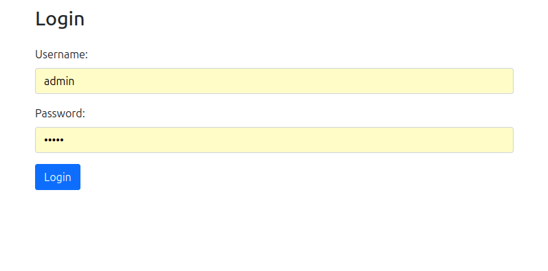
| Ze względów bezpieczeństwa, zdecydowanie zaleca się zmianę domyślnego hasła administratora bezpośrednio po pierwszym zalogowaniu do systemu. W przypadku pozostawienia niezmienionego domyślnego hasła, przy każdym kolejnym logowaniu system będzie wyświetlał stosowne ostrzeżenie bezpieczeństwa, przypominając o konieczności jego aktualizacji. |
Panel główny aplikacji
Po pomyślnym zalogowaniu użytkownik zostaje przekierowany na stronę główną aplikacji, która prezentuje się w formie przejrzystego dashboardu z kafelkami. Każdy kafelek reprezentuje dostęp do konkretnej sekcji funkcjonalnej aplikacji, umożliwiając intuicyjną nawigację między różnymi modułami systemu. Układ kafelków został zaprojektowany tak, aby najczęściej używane funkcje były łatwo dostępne.
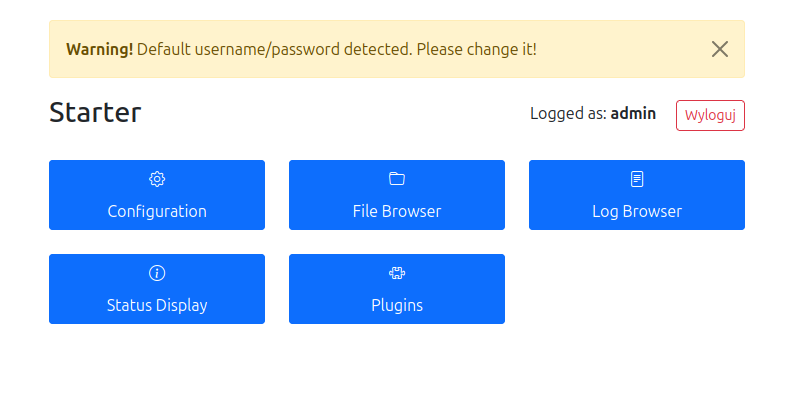
| Na górze interfejsu wyświetlane jest ostrzeżenie o niezmienionych domyślnych danych logowania (nazwa użytkownika/hasło), które pozostaje widoczne do momentu ich aktualizacji przez administratora. |
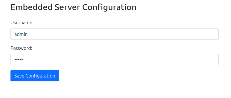
Zarządzanie konfiguracją użytkowników
Moduł edycji konfiguracji umożliwia administratorowi zarządzanie kontami użytkowników systemu, w tym zmianę nazw użytkowników oraz haseł. Funkcjonalność ta jest kluczowa dla utrzymania bezpieczeństwa systemu. Po wprowadzeniu zmian w konfiguracji użytkowników konieczne jest zapisanie ustawień i wykonanie restartu aplikacji, aby nowe dane zostały załadowane. Po pomyślnej aktualizacji danych logowania, ostrzeżenia bezpieczeństwa przestają być wyświetlane w interfejsie.
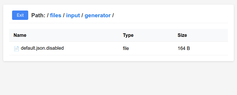
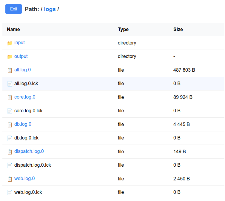
System zarządzania plikami konfiguracyjnymi
Przeglądarka plików stanowi zaawansowane narzędzie do zarządzania konfiguracją aplikacji. Moduł ten zapewnia pełny dostęp do zawartości folderu configs, w którym przechowywane są wszystkie pliki konfiguracyjne systemu. Użytkownik może przeglądać hierarchiczną strukturę katalogów, nawigować między folderami oraz bezpośrednio edytować pliki konfiguracyjne w formacie JSON. Narzędzie to jest niezbędne do fine-tuningu parametrów aplikacji oraz dostosowywania jej zachowania do specyficznych wymagań środowiska produkcyjnego.
System monitorowania logów
Przeglądarka logów oferuje kompleksowy dostęp do systemu logowania aplikacji i wszystkich jej modułów. Narzędzie to umożliwia przeglądanie zawartości folderu logs, w którym przechowywane są pliki dziennika zdarzeń. Funkcjonalność ta jest kluczowa dla diagnozy problemów, monitorowania wydajności oraz analizy zachowania systemu w czasie rzeczywistym. Administratorzy mogą łatwo lokalizować i analizować konkretne zdarzenia, błędy lub anomalie w działaniu aplikacji.
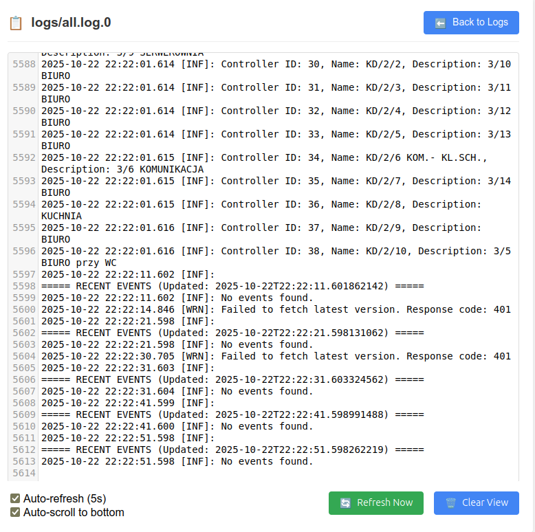
Podgląd logów w czasie rzeczywistym
Moduł podglądu logów zapewnia możliwość śledzenia aktywności aplikacji oraz wszystkich jej modułów w czasie rzeczywistym. Funkcja ta jest wyposażona w zaawansowane opcje, takie jak automatyczne odświeżanie interfejsu co 5 sekund oraz automatyczne przewijanie do najnowszych wpisów. Te funkcjonalności znacząco ułatwiają monitorowanie bieżącej aktywności systemu oraz szybkie wykrywanie potencjalnych problemów podczas normalnej eksploatacji aplikacji.
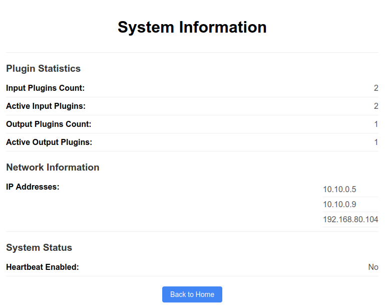
Panel informacji systemowej
Sekcja informacji o systemie prezentuje kompleksowy przegląd stanu infrastruktury aplikacji. Panel ten wyświetla kluczowe informacje techniczne, w tym wszystkie adresy IP interfejsów sieciowych serwera, dokładne wersje wszystkich komponentów systemu oraz szczegółowe statystyki dotyczące liczby uruchomionych i aktywnych modułów. Te informacje są niezbędne dla administratorów systemu podczas diagnostyki, planowania aktualizacji oraz monitorowania ogólnego stanu zdrowia aplikacji.
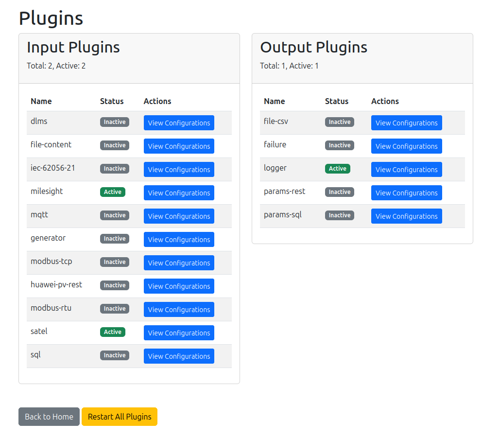
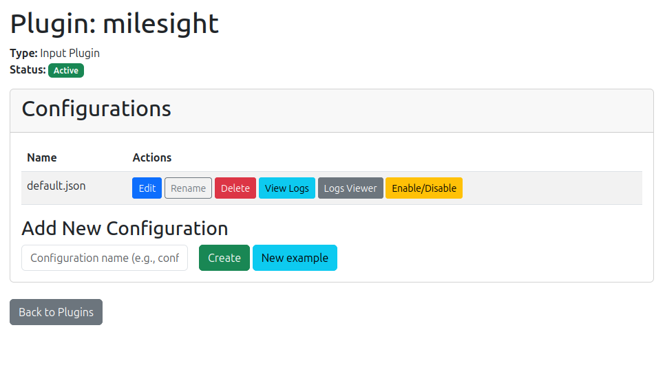
Zarządzanie wtyczkami systemu
Lista wtyczek stanowi centralne miejsce zarządzania wszystkimi modułami rozszerzającymi funkcjonalność aplikacji. Interface ten prezentuje w przejrzystej formie tabelarycznej wszystkie dostępne wtyczki, podzielone na kategorie wejściowe (Input) oraz wyjściowe (Output), wraz z ich bieżącymi statusami działania. Każda wtyczka wyświetlana jest z informacjami o jej stanie (aktywna/nieaktywna) oraz dostępnymi akcjami.
Przycisk View configurations umożliwia przejście do szczegółowego panelu konfiguracji wybranego modułu, gdzie można zarządzać jego ustawieniami. Szczególnie użyteczny jest przycisk Restart all plugins, który pozwala na restart wszystkich modułów bez konieczności zatrzymywania całej aplikacji. Ta funkcjonalność jest niezbędna podczas wdrażania zmian konfiguracyjnych, ponieważ automatycznie wczytuje nowe ustawienia i aktualizuje parametry działania wszystkich wtyczek.
Szczegółowe zarządzanie konfiguracją wtyczek
Panel szczegółów konfiguracji wtyczki oferuje zaawansowane narzędzia do kompleksowego zarządzania poszczególnymi modułami. W górnej części interfejsu prezentowana jest lista wszystkich plików konfiguracyjnych powiązanych z daną wtyczką, wraz z możliwością ich bezpośredniej edycji. Administrator ma do dyspozycji funkcje restartu konkretnej wtyczki (bez wpływu na inne moduły), bezpośredni dostęp do dedykowanych logów danego modułu oraz możliwość włączania i wyłączania poszczególnych konfiguracji wtyczki.
Dolna część panelu zawiera intuicyjny formularz dodawania nowych konfiguracji, który umożliwia utworzenie nowego pliku konfiguracyjnego dla wtyczki. Użytkownik może wybrać między utworzeniem pustego pliku konfiguracyjnego (do wypełnienia od podstaw) lub skorzystać z gotowego szablonu opartego na przykładowej konfiguracji, co znacząco przyspiesza proces wdrażania nowych funkcjonalności.
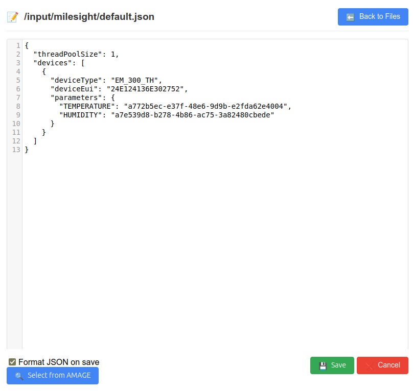
Edytor plików konfiguracyjnych
Wbudowany edytor konfiguracji stanowi zaawansowane narzędzie do modyfikacji plików konfiguracyjnych w formacie JSON. Edytor oferuje składnię highlighting, walidację struktury JSON oraz wbudowane mechanizmy sprawdzania poprawności składni. Po zakończeniu edycji i zapisaniu pliku, konieczne jest zrestartowanie odpowiedniego modułu lub całej aplikacji, aby wprowadzone zmiany zostały załadowane i zaczęły obowiązywać w systemie. Proces ten zapewnia spójność konfiguracji i bezpieczne wdrażanie zmian.
Available modules and their configuration
Ta część instrukcji opisuje dostępne moduły, z rozróżnieniem, który moduł jest dostawcą, a który odbiorcą.
Wejściowa wtyczka: pvd-input-IEC-62056-21
Nazwa modułu: iec-62056-21
This module allows reading measurements from IEC-62056-21-compliant electricity meters. The module reads data from serial ports, in at most one thread per port.
Przykładowa ścieżka do pliku konfiguracyjnego: <user.home>/configs/input/iec-62056-21/default.json (zamiast default dopuszczalna jest inna, własna nazwa).
 {
    "sleepTime": 30,
    "verboseMode": false,
    "showRawTransmission": false,
    "threadPoolSize":2,
    "sleepBetweenQuerying": 0,
    "disableDelayForUnavailableDevices": false,
    "meterGroupConfigs" : [
        {
            "portName":"/dev/ttyr00",
            "sleepBetweenQuerying": 30,
            "sleepTime": 15,
            "active":true,
            "globalMultipliers":[
            {
                "name":"standard",
                "configs" : {
                    "1.6.0":"{value}*{multiplier}",
                    "1.8.0":"{value}*{multiplier}"
                }
            },
            {
                "name":"pozyton",
                "configs" : {
                    "107":"{value}*{multiplier}",
                    "109":"{value}*{multiplier}"
                }
            }
            ],
            "configs": [
                {
                    "deviceAddress":"51034542",
                    "initialBaudRate": 2400,
                    "timeout": 10000,
                    "active":false,
                    "multiplier":"sqrt(4)/(3^2+2)",
                    "multiplierTemplateName":"standard",
                    "multipliersMap": {
                        "1.6.1":"{value}*12",
                        "1.8.1":"{value}*{multiplier}"
                    }
                },
                {
                    "deviceAddress":"023-0000691",
                    "initialBaudRate": 9600,
                    "timeout": 10000,
                    "meterType": "POZYTON"
                }
            ]
        },
        {
            "portName":"/dev/ttyr02",
            "configs": [
                {
                    "deviceAddress":"51204143",
                    "initialBaudRate": 2400,
                    "timeout": 10000
                },
                {
                    "deviceAddress":"51255055",
                    "initialBaudRate": 2400,
                    "timeout": 10000
                }
            ]
        }
    ]
}-
sleepTime - (int) time interval in seconds between downloading data from the counter, default
60s, can be configured globally and then overridden for a given port configuration -
verboseMode - (boolean) counter mode giving more information, default
false. -
showRawTransmission - (boolean) shows raw data transmission from the counter, default is
false -
threadPoolSize - (int) the maximum size of the thread pool used to read data from the counters. If it is larger than the number of ports, it is truncated to that number.
-
disableDelayForUnavailableDevices - (boolean) disables automatic delay for devices that are not available (e.g. no response). Facilitates diagnostics and connection of such devices, as the system will not delay further readings in case the device does not respond. The default delay is 10 readings.
-
globalMultipliers - (list) containing a unique name (name) as well as a map with the address of the read value to the way the value is to be converted. It must contain
{value}→ i.e. the read value and optionally{multiplier}i.e. the expression from the given counter. -
portName - (String) the name of the port on which the counter is located (for Linux these ports are
tty, for windowsCOM, and for moxyttyr). -
deviceAddress - (String) the serial number of the device, an address unique to the device through which we can identify it.
-
initialBaudRate - (int) value specific to the counter type, this is the operating frequency specific to the port as well.
-
sleepBetweenQuerying - (int) time interval in seconds between polling of individual counters on a given port.
-
meterType - (String) type of the meter, if it conforms to the standard, the field can be omitted. Available values:
STANDARD(default),POZYTON. -
active - (boolean) whether the port is active, default
true, optionally you can disable, in addition when the port is active you can disable the individual counter. -
multiplier - (String), the multiplier of a given counter. This can be a single value as well as an expression.
-
multiplierTemplateName - (String) the name from the template being used, this must be the name appearing in globalMultipliers in the name field * multipliersMap - (Map) a unique map for the counter with value converters. Must be present
{value}otherwise the default value read from the counter is returned. If the same parameter is present in globalMultipliers it is overwritten with this converter.
If the device does not respond (no communication) and this effect occurs for 3 consecutive reading attempts, the system automatically stops trying to communicate with the device for 10 consecutive readings. This allows the system to reduce blocking of communication with other devices on the same bus. After a correct reading, the system automatically resumes reading at the set maximum frequency. We can disable this behavior (e.g. for diagnostic purposes) using the global option disableDelayForUnavailableDevices
|
Wejściowa wtyczka: pvd-input-modbus-tcp
Nazwa modułu: modbus-tcp
This module allows you to read values after the modbus TCP protocol (e.g. from the inverter).
Przykładowa ścieżka do pliku konfiguracyjnego: <user.home>/configs/input/modbus-tcp/default.json (zamiast default dopuszczalna jest inna, własna nazwa, np. opisująca to konkretne źródło danych).
Version 1 configuration.
Version 1 of the configuration describes communication using basic data types. Preserved for compatibility with existing configurations. Recognized by three parameters in the register definition, e.g. 0:float:100.
 {
      "debug": false,
      "devices":[
            {
                "ip":"192.168.1.104",
                "port":502,
                "sleepTime":10,
                "description":"Falownik Testowy",
                "enabled":"true",
                "useLoHiWordOrder": "false",
                "data": {
                    "0:float:100":"fd005850-86c9-498e-8ab2-d3d7a739daa6",
                    "1:int:0":"2a9ed604-bac9-44b9-84b0-01f91f3b4ee4",
                    "2:float:100":"b063bc0a-06ec-40c8-a5fa-721275443388",
                    "3:float:10":"6028f30e-205a-4fa6-8e9a-0fc4ed11d979",
                    "4:float:10":"46f2b46c-da21-425a-a118-95a8c09b4422",
                    "5:float:10":"38ce3bb2-33b9-49ad-8d85-12eec0020653",
                    "6:int:0":"a2f75e59-96df-4b83-81fe-8e6e96e24330",
                    "7:float:10":"41be100f-ba9a-41a2-bd51-801fc922157f"
                }
            },

            {
                "ip":"192.168.1.105",
                "port":502,
                "sleepTime":10,
                "description":"Falownik Testowy 2",
                "enabled":"false",
                "data": {
                    "0:float:100":"fd005850-86c9-498e-8ab2-d3d7a739daa6",
                    "1:int:0":"2a9ed604-bac9-44b9-84b0-01f91f3b4ee4",
                    "2:float:100":"b063bc0a-06ec-40c8-a5fa-721275443388",
                    "3:float:10":"6028f30e-205a-4fa6-8e9a-0fc4ed11d979",
                    "4:float:10":"46f2b46c-da21-425a-a118-95a8c09b4422",
                    "5:float:10":"38ce3bb2-33b9-49ad-8d85-12eec0020653",
                    "6:int:0":"a2f75e59-96df-4b83-81fe-8e6e96e24330",
                    "7:float:10":"41be100f-ba9a-41a2-bd51-801fc922157f"
                }
            }

        ]
}
Version 2 configuration.
Version 2 of the configuration describes communication using all known MODBUS data types. It tries to handle all data types.
 {
      "debug": false,
      "devices":[
            {
                "ip":"192.168.1.104",
                "port":502,
                "unitId":1,
                "addressShift":-1,
                "sleepTime":10,
                "useLoHiWordOrder": "false",
                "description":"Falownik Testowy",
                "enabled":"true",
                "data": {
                    "40072:uint32:Power Active:2": "b2ddc792-cf40-42b7-b9ce-82eb68928ac3",
                    "40005:string32:Manufacturer:0": "c2ddc792-cf40-42b7-b9ce-82eb68928ac3"
                }
            }

        ]
 }
Definition data:
-
debug - (boolean) flag enabled allows logging in logs/console information from the communication library and displaying data sent and received in HEX format
General data contains information about individual devices.
-
ip - (String) ip address of the device.
-
port - (int) port on which we will connect (standard 502).
-
unitId - (int) modbus unit number (usually 1).
-
addressShift - (int) address shift, e.g. -1. Applied always in case of reading. Allows definition in mapping the actual addresses from the documentation and at the same time the appropriate shift according to the protocol of the device. <Option>.
-
addressBase - (int) base value of the address. Always added to the address. <Option>.
-
description - (String) description of the device.
-
When reading a DWORD (two registers), by default we use HiLo register alignment, that is, the highest byte first and then down to the lowest byte. With this option enabled, we use the reverse alignment BUT only for registers. That is, if we read bytes from TWO registers
[A] [B] [C] [D]the HiLo alignment will beMSB [A] [B] [C] [D] LSB, while for LoHi alignment it will beMSB [C] [D] [A] [B] LSB. -
sleepTime - (int) time interval in seconds to read the protocol.
-
enabled - (boolean) flag whether we want to read the device.
-
data - (Map<String, UUID>) Map of the registers we are going to read, and the UUID under which they are to be cast.
Register map format, contains a pair of register configuration and UUID of parameter settings.
Version 1 configuration.
The registry configuration consists of three fields:
-
register number (e.g., 2003)
-
data type - int or float
-
divisor - determines by what number the reading will be divided, for example, for a reading of register 1000 with the value 1234 of float type and divisor 100 we get the result 12.34
Version 2 configuration.
The register configuration consists of 4 fields:
-
register number (e.g., 2003)
-
data type - uint16, uint32, uint64, int16, int32, bitfield16, enum16, acc32, float32, string32, string16
-
description - description for the user (appears in the logs)
-
divisor - determines by what number the reading will be divided, for example, for a reading of register 1000 with the value 1234 of float type and divisor 100 we get the result 12.34. We always use 2 characters after the decimal point
Wejściowa wtyczka: pvd-input-modbus-rtu
Nazwa modułu: modbus-rtu
This module allows you to read values from devices after the modbus RTU protocol, that is, the MODBUS protocol over serial buses of the RS-232/RS-485 type. In the documentation, we omit the mechanism of physical connection of the RS device/converter to a given system, on which the PVD application is installed.
| Intermediary devices such as Moxa N-Port (or similar) can also be used for connections. In this case, there is usually additional utility software from the respective manufacturer to make the serial ports of the device available as virtual serial ports whether in a Windows or Linux environment. Refer to the manufacturer’s documentation to connect/map the appropriate ports. |
Przykładowa ścieżka do pliku konfiguracyjnego: <user.home>/configs/input/modbus-rtu/default.json (zamiast default dopuszczalna jest inna, własna nazwa, np. opisująca to konkretne źródło danych). Może istnieć dowolna liczba takich konfiguracji np. z podziałem na poszczególne porty szeregowe.
Configuration.
The configuration is divided into a data tree. Physical devices (communication units) are grouped into communication (serial) ports with the same communication parameters. That is, we have a hierarchy of general configuration → ports → devices.
An example configuration file is provided below. It contains the definition of one serial port and one device connected to this port.
 {
    "sleepTime": 30,
    "debug": false,
    "threadPoolSize": 1,
    "sleepBetweenQuerying": 2,
    "disableDelayForUnavailableDevices": false,
    "ports": [
        {
            "sleepTime": 3,
            "sleepBetweenQuerying": 1,
            "active": true,
            "port": "/dev/ttyUSB0",
            "baudRate": 9600,
            "dataBits": 8,
            "stopBits": 1,
            "parity": "None",

            "devices": [
                {
                    "name": "Test modbus RTU device",
                    "description": "additional description for the device",
                    "active": true,
                    "unitId": 1,
                    "addressShift": 0,
                    "addressBase": 0,
                    "useLoHiWordOrder": true,
                    "sleepTime": 5,
                    "data": {
                        "0:float32:Current Voltage - clamp A:0": "97c95bd0-abe4-4770-bdef-23b6f075cd0f",
                        "2:float32:Current Voltage - clamp B:100": "97d95bd0-abe4-4770-bdef-23b6f075cd0f"
                    }
                }
            ]
        }
    ]
}| It was assumed that one serial port has its definitions, i.e. bit rate, communication parameters uniform for all devices connected to this port. This is due to the characteristics of the data link. Different speeds/parameters can cause erroneous operation of devices pinned on the same bus. |
General definition data:
-
sleepTime - (int) time interval in seconds between downloading data from the device, default
60s, can be configured globally and then overridden for a given port configuration -
debug - (boolean) flag enabled allows logging in logs/console information from the communication library and displaying data sent and received in HEX format
-
threadPoolSize - (int) the maximum thread pool size used to read data from devices. If it is larger than the number of ports, it is truncated to that number.
-
sleepBetweenQuerying - (int) time interval in seconds between polling of individual devices on a given port. It can be overridden on individual ports.
-
disableDelayForUnavailableDevices - (boolean) disables automatic delay for devices that are not available (e.g. no response). Facilitates diagnostics and connection of such devices, as the system will not delay further readings in case the device does not respond. The default delay is 10 readings.
Serial port data:
-
sleepTime - (int) time interval in seconds between downloading data from the device,
-
sleepBetweenQuerying - (int) time interval in seconds between polling of individual devices on a given port.
-
active - whether the port is active and we read data from it
-
port - port name, e.g. COM1, /dev/ttyUSB0, etc.
-
baudRate - bit rate, e.g. 9600
-
dataBits - number of data bits - 7/8
-
stopBits - number of stop bits - 0/1
-
parity - evenness of communication - values: Even, Mark, None, Odd, Space
Data of the individual device:
-
name - (String) device name (appears in logs).
-
description - (String) device description - descriptive field for configuration.
-
active - (boolean) flag whether we want to read the device.
-
unitId - (int) modbus unit number (usually 1).
-
addressShift - (int) address shift, e.g. -1. Applied always in case of reading. Allows definition in mapping the actual addresses from the documentation and at the same time the appropriate shift according to the protocol of the device. <Option>.
-
addressBase - (int) base value of the address. Always added to the address. <Option>.
-
When reading a DWORD (two registers), by default we use HiLo register alignment, that is, the highest byte first and then down to the lowest byte. With this option enabled, we use the reverse alignment BUT only for registers. That is, if we read bytes from TWO registers
[A] [B] [C] [D]the HiLo alignment will beMSB [A] [B] [C] [D] LSB, while for LoHi alignment it will beMSB [C] [D] [A] [B] LSB. -
sleepTime - (int) time interval in seconds to read the protocol.
-
data - (Map<String, UUID>) Map of the registers we are going to read, and the UUID under which they are to be cast.
The format of the register map, contains a pair of register configurations and UUID of the parameter settings are in accordance with version 2 of the Modbus TCP configuration, ie.
Version (2) configuration.
The register configuration consists of 4 fields:
-
register number (e.g., 2003)
-
data type - uint16, uint32, uint64, int16, int32, bitfield16, enum16, acc32, float32, string32, string16
-
description - description for the user (appears in the logs)
-
divisor - determines by what number the reading will be divided, for example, for a reading of register 1000 with the value 1234 of float type and divisor 100 we get the result 12.34. We always use 2 characters after the decimal point
If the device does not respond (no communication) and this effect occurs for 3 consecutive reading attempts, the system automatically stops trying to communicate with the device for 10 consecutive readings. This allows the system to reduce blocking of communication with other devices on the same bus. After a correct reading, the system automatically resumes reading at the set maximum frequency. We can disable this behavior (e.g. for diagnostic purposes) using the global option disableDelayForUnavailableDevices
|
Wejściowa wtyczka: pvd-file-content-reader
Nazwa modułu: file-content
This module allows periodic reading of values from a file. It allows, for example, to read data stored in the /proc system or in other files, e.g. parameter values of 1-Wire sensors using the file system view.
Przykładowa ścieżka do pliku konfiguracyjnego: <user.home>/configs/input/file-content/default.json (zamiast default dopuszczalna jest inna, własna nazwa, np. opisująca to konkretne źródło danych).
 {
  "pathFile":"/path/to/file",
  "sleepTime":10,
  "uuid":"f01ec5fd-117c-4cbf-aed8-1ab6066bd4c7",
  "charsetName":"UTF-8"
}-
pathFile - (path) path to the file from which we want to read data.
-
sleepTime - (int) time interval in seconds to read from the file.
-
uuid - (uuid) unique parameter uuid number for this file. (same as in the application).
-
charsetName - (String) optional choice of encoding, default
UTF-8.
Odbiorca: pvd-output-params-rest
Nazwa modułu: params-rest
This module allows you to forward messages to the selected Sync server.
Przykładowa ścieżka do pliku konfiguracyjnego: <user.home>/configs/output/params-rest/default.json. (zamiast default dopuszczalna jest inna, własna nazwa, np. opisująca odbiorcę).
 {
    "connectionTimeout": 5,
    "skipTime": 180,
    "restConfig": {
        "apiKey": "666f6f",
        "apiSecret": "626172",
        "protocol": "http",
        "host": "localhost",
        "context": "",
        "port": 5000,
        "deviceUUID": "26f4c3a7-3820-4d0f-844e-134da324a40b"
    }
 }
-----
connectionTimeout - (int) time (in seconds) after which the connection will be considered failed, default
5. Prevents the output from blocking. -
skipTime - (int) the time (in seconds) that must pass after a failed connection before a retry is made, default is
180. Prevents the output from blocking.
The value of the restConfig field indicates the configuration of the connection to the Sync server. If it is the same server with which the application was paired, just insert the configuration from the assetsync.conf file here.
-
apiKey - (String) apiKey of the device
-
apiSecret - (String) apiSecret of the device
-
protocol - (String) type of protocol used to send data
-
host - (String) assetsync server address
-
context - (String) assetsync server context
-
port - (int) port number used to communicate with assetsync
-
deviceUUID - (uuid) unique uuid of the device
Wejściowa wtyczka: pvd-input-test
Nazwa modułu: example
Generates random data at intervals.
Przykładowa ścieżka do pliku konfiguracyjnego:
<user.home>/configs/input/example/default.json. (zamiast default dopuszczalna jest inna, własna nazwa).
All fields are optional.
 {
    "threadPoolSize": 1,
    "generatorsQuantity": 1,
    "sleepTime": 1000,
    "payloadSize": 1,
    "parameterUUID": "ef466d4f-ec72-44c5-939c-287e7646b125"
}-
threadPoolSize - (int) number of threads used to generate the value, default is 1.
-
generatorsQuantity - (int) number of generators.
-
sleepTime - (int) time (in milliseconds) how often to query the generator for a value.
-
payloadSize - (int) number of generated values.
-
parameterUUID - (UUID) parameter to which the generated value applies
Odbiorca: pvd-output-test
Nazwa modułu: example
Logs all received messages, does not forward them.
Przykładowa ścieżka do pliku konfiguracyjnego:
<user.home>/configs/output/example/default.json. (zamiast default dopuszczalna jest inna, własna nazwa).
This module does not allow configuration, the configuration file always looks the same:
{}
Wejściowa wtyczka: pvd-input-dlms
Nazwa modułu: dlms
The DLMS provider allows communication with devices using the DLMS protocol. Configuring the provider involves specifying access parameters for the devices and a list of OBIS codes that will be read from the devices.
 {
    "sleepTime": 30,
    "threadPoolSize":2,
    "obisCodes": ["1.1.2.6.0.255"],
    "meterGroupConfigs" : [
        {
            "portName":"/dev/ttyUSB0",

            "configs" : [
                {
                    "deviceAddress":"9569",
                    "initialBaudRate": 9600,
                    "timeout": 10000,
                    "logicalId":1,
                    "clientId":16
                }
            ]
        }
    ]
}-
threadPoolSize - (int) number of threads used to generate the value, default is 1.
-
obisCodes - (list) list of OBIS codes that will be read from devices
-
meterGroupConfig - (struct) meter configuration structure
-
deviceAddress - (string) device serial number
-
logicalId - (int) logical ID of the device within the communication
-
clientId (int) ID of the access client
Mapping to parameters implemented using sync mapping configuration.
Dostawca: pvd-input-sql
Nazwa modułu: sql
Mechanism for retrieving data from an external source in the form of a table with measurements. Provider definition implemented using a sample configuration with access to MS SQL server:
 {
    "dbDriver":"com.microsoft.sqlserver.jdbc.SQLServerDriver",
    "dbUrl":"jdbc:sqlserver://100.100.100.100\\INSTANCE:1433;databaseName=database;",
    "dbUser":"amage",
    "dbPassword":"amage",
    "tableName":"POMIARY",
    "timeBetweenDispatch": 120
}-
dbDriver - JDBC driver class for access. MS SQL server and PostgreSQL available.
-
dbUrl - URL in JDBC format to access the database
-
dbUser - user to authorize access
-
dbPassword - user password for access authorization
-
tableName - name of the source table from which we retrieve data
-
timeBetweenDispatch - time between scans of the source table in seconds.
The columns in the source table must have the following structure:
-
DateTime - date - reading date
-
TagName - string - parameter name
-
Value - string - parameter value
| After reading, the entire contents of the measurement table are deleted (in a given session). |
Mapping to parameters implemented using sync mapping configuration.
Wyjściowa wtyczka: pvd-output-params-sql
Nazwa modułu: params-sql
Receives parameter data from the Sync system and passes it to external tables with a fixed structure.
The columns in the source table must have the following structure:
-
[1] - date - reading date
-
[2] - string - parameter name
-
[3] - string - parameter value
Example configuration file:
 {
    "dbDriver":"com.microsoft.sqlserver.jdbc.SQLServerDriver",
    "dbUrl":"jdbc:sqlserver://100.100.100.100\\INSTANCE:1433;databaseName=database;",
    "dbUser":"amage",
    "dbPassword":"amage",

    "targetParams": [
        {
            "valueName":"00MKA10CE901",
            "uuid":"37073696-74cf-4a40-847f-bae4a2debedc",
            "multiplier":1
        },
        {
            "valueName":"00AEA00CE902",
            "uuid":"65a56440-018b-4ddd-b1f9-ae6cce642e31",
            "multiplier":1
        },
        {
            "valueName":"00AEA00CE901",
            "uuid":"ee6e896d-a0ab-4932-8635-5f25e6e9ef63",
            "multiplier":1
        }

    ],

    "table" : [
        {
            "tableName":"dbo.Liczniki_E_01M",
            "time":60
        },
        {
            "tableName":"dbo.Liczniki_E_15M",
            "time":900
        }
    ]
}-
dbDriver - JDBC driver class for access. MS SQL server and PostgreSQL available.
-
dbUrl - URL in JDBC format to access the database
-
dbUser - user to authorize access
-
dbPassword - user password for access authorization
-
targetParams - target parameters for export
-
table - tables to which data will be exported
-
valueName - name of the target parameter to be entered into the target table
-
uuid - UUID of parameter settings in the AMAGE system for export to an external system
-
multiplier - multiplier to perform in the case of numerical data
-
tableName - name of the table to be exported
-
time - data sending period
This approach allows exporting data at different times to different tables.
Wyjściowa wtyczka: pvd-failure
Nazwa modułu: failure
A test data receiver that on receiving any message generates a DispatchResult.FAILURE response.
Dostawca: pvd-input-huawei-pv-rest
Nazwa modułu: huawei-pv-rest
A mechanism for downloading data on inverters used in photovoltaic systems. Communication takes place via an HTTP REST interface to an external server from Huawei (at the time of writing the documentation servers in the domain fusionsolar.huawei.com). This means that the application must have access to the aforementioned address and descendant addresses in this domain to allow access to this data.
 {
    "devices": [
        {
            "description": "Huawei PV - SUN2000-15KTL-M0 - SN: 123",
            "userName": "user",
            "systemCode": "systemcode",
            "stationCode": "xxx",
            "deviceId": 0,
            "deviceTypeId": 0,
            "sleepTime": 10,
             "data": {
                 "grid_frequency:Grid frequency:0": "d119b575-0604-4404-b954-017a828fe98d"
             },
            "enabled": true
        }
    ]
}-
description - Description of the device
-
userName - user to log in to the REST system
-
systemCode - system code for logging into the REST system
-
stationCode - station identifier
-
deviceId - device number
-
deviceTypeId - device type
-
sleepTime - the time of breaks between readings (seconds)
-
enabled - enable/disable configuration
-
data - parameter mapping data to UUID of parameter settings
| The configuration skeleton can be generated directly in the AMAGE application for a given device. In the context menu of the resource there are actions for generating the skeleton file. |
After creating the aforementioned backbone file, you can proceed to further configuration. The most important thing is to have userName/systemCode data obtained from Huawei system implementers (or directly from Huawei Solar). We enter this data into the configuration.
| If you don’t know the station ID, device ID or device type, leaving the default values of "xxx" or 0, the system at startup will display all available data from which you can copy this information. This information can also be copied from Huawei’s data access web interface. |
After filling in all the data, the parameter settings mappings should be configured accordingly. It consists of three segments:
<function number>:<name>:<scaling>
Where:
-
Function number is the name of the function from the dictionary below. Corresponds to parameters readable by devices
-
Name - auxiliary parameter, displayed in PVD logs and from the parameter configuration in the AMAGE application
-
Scaling - 0 → no scaling. If > 0, the measured value will be DIVIDED into the given value. This allows, for example, reading data in kWh and converting it to MWh immediately before sending it to the main system.
Wyjściowa wtyczka: pvd-output-csv
Nazwa modułu: file-csv
The module allows you to save data locally in the PVD application runtime environment. Data is received by standard methods from data providers and then saved in a CSV format file (semicolon separator ;) in the destination directory. When the separateFiles option is enabled to true, the system saves the messages in separate files for each UUID after receiving them.
In the case of separateFiles = false, a file named output.csv is created in the destination directory and values in the format are written to it:
-
Timestamp (ISO)
-
Parameter UUID
-
Read parameter value
e.g.
2022-05-12T13:10:44.888;b89da96b-d444-4adc-93b7-b9b7e0798c12;11341;
In the case of separateFiles = true separate files are created. For the aforementioned case, a file named b89da96b-d444-4adc-93b7-b9b7e0798c12.csv and sample content (one record) will be created in the target directory:
2022-05-12T13:10:44.888;11341;
| Files are completed, i.e. if they exist and are not empty then the values will be added to the end of the file |
Configuration example:
 {
    "resultPath": "/home/user/result_folder",
    "separateFiles": true
 }
Wejściowa wtyczka - OPC-UA
Nazwa modułu: opc-ua
Mechanizm pobierania danych z serwerów OPC-UA. Moduł pozwala na połączenie z serwerem OPC-UA, autoryzację oraz cykliczny odczyt wybranych węzłów danych.
Przykładowa ścieżka do pliku konfiguracyjnego: <user.home>/configs/input/opc-ua/default.json (zamiast default dopuszczalna jest inna, własna nazwa, np. opisująca to konkretne źródło danych).
{
    "endpointUrl": "opc.tcp://localhost:4840",
    "readIntervalMs": 1000,
    "username": "opcuser",
    "password": "opcpassword",
    "nodes": [
        {
            "nodeId": "ns=2;s=Device1.Temperature",
            "parameterUuid": "f01ec5fd-117c-4cbf-aed8-1ab6066bd4c7"
        },
        {
            "nodeId": "ns=2;s=Device1.Pressure",
            "parameterUuid": "a2b3c4d5-e6f7-8901-2345-6789abcdef01"
        }
    ]
}-
endpointUrl - (String) adres URL serwera OPC-UA w formacie
opc.tcp://host:port -
readIntervalMs - (int) interwał odczytu danych w milisekundach, domyślnie
1000 -
username - (String) nazwa użytkownika do autoryzacji (opcjonalne)
-
password - (String) hasło użytkownika do autoryzacji (opcjonalne)
-
nodes - (list) lista węzłów OPC-UA do odczytu
Konfiguracja węzła OPC-UA:
-
nodeId - (String) identyfikator węzła OPC-UA w standardowym formacie (np.
ns=2;s=Device1.Temperature) -
parameterUuid - (UUID) unikalny identyfikator parametru w systemie AMAGE, do którego będą mapowane dane z tego węzła
Nadawca - Milesight IoT LoRaWAN
Nazwa modułu: milesight
Mechanizm odbierania danych z urządzeń IoT firmy Milesight przez interfejs HTTP webhooks. Moduł udostępnia endpointy HTTP do odbierania danych telemetrycznych z urządzeń LoRaWAN, takich jak czujniki temperatury i wilgotności.
Przykładowa ścieżka do pliku konfiguracyjnego: <user.home>/configs/input/milesight/default.json (zamiast default dopuszczalna jest inna, własna nazwa, np. opisująca to konkretne źródło danych).
{
    "threadPoolSize": 1,
    "devices": [
        {
            "deviceType": "EM_300_TH",
            "deviceEui": "24e124136e302752",
            "parameters": {
                "TEMPERATURE": "f01ec5fd-117c-4cbf-aed8-1ab6066bd4c7",
                "HUMIDITY": "a2b3c4d5-e6f7-8901-2345-6789abcdef01"
            }
        }
    ]
}-
threadPoolSize - (int) rozmiar puli wątków do obsługi żądań HTTP, domyślnie
1 -
devices - (list) lista urządzeń Milesight skonfigurowanych do odbioru danych
Konfiguracja urządzenia Milesight:
-
deviceType - (enum) typ urządzenia Milesight. Dostępne wartości:
EM_300_TH(czujnik temperatury i wilgotności) -
deviceEui - (String) unikalny identyfikator urządzenia (Device EUI) w sieci LoRaWAN
-
parameters - (map) mapowanie parametrów urządzenia na UUID parametrów w systemie AMAGE
Dostępne parametry dla urządzenia EM_300_TH:
-
TEMPERATURE - temperatura w stopniach Celsjusza
-
HUMIDITY - wilgotność względna w procentach
Moduł udostępnia następujące endpointy HTTP, do których wysyła bramka LoRaWAN Milesight dane telemetryczne:
-
/pvd-input-milesight/data - endpoint do odbierania danych telemetrycznych (metoda POST)
-
/pvd-input-milesight/status - endpoint statusu modułu (metoda GET)
-
/pvd-input-milesight/error - endpoint testowy do generowania błędów
Format danych wejściowych (JSON):
{
    "applicationID": 1,
    "devEUI": "24e124136e302752",
    "deviceName": "temperature - 01",
    "humidity": 39,
    "temperature": 21.2
}
Należy skonfigurować bramkę LoRaWAN Milesight, aby wysyłała dane telemetryczne do endpointu /pvd-input-milesight/data aplikacji PVD. W przeciwnym razie moduł nie będzie odbierał żadnych danych.
|
Wyjściowa wtyczka - interfejs webhooks
Nazwa modułu: webhook
Mechanizm wysyłania danych do zewnętrznych systemów przez interfejs HTTP webhooks. Moduł przekształca otrzymane dane na format JSON i wysyła je metodą POST do skonfigurowanego adresu URL.
Przykładowa ścieżka do pliku konfiguracyjnego: <user.home>/configs/output/webhook/default.json (zamiast default dopuszczalna jest inna, własna nazwa, np. opisująca docelowy system).
{
    "outputWebhook": "https://example.com/api/data"
}-
outputWebhook - (String) adres URL zdalnego systemu, do którego będą wysyłane dane w formacie JSON
Format wysyłanych danych JSON:
[
    {
        "timestamp": "2025-01-24T10:30:15",
        "valueUUID": "f01ec5fd-117c-4cbf-aed8-1ab6066bd4c7",
        "valueString": "21.5"
    },
    {
        "timestamp": "2025-01-24T10:30:15",
        "valueUUID": "a2b3c4d5-e6f7-8901-2345-6789abcdef01",
        "valueString": "65.2"
    }
]
Parametry wysyłanych danych:
-
timestamp - znacznik czasowy w formacie ISO LocalDateTime
-
valueUUID - unikalny identyfikator parametru w systemie AMAGE
-
valueString - wartość parametru w formacie tekstowym
Moduł automatycznie obsługuje:
-
Timeout połączenia (5 sekund)
-
Certyfikaty SSL self-signed
-
Weryfikację statusu odpowiedzi HTTP (200-299 = sukces)
-
Logowanie błędów komunikacji
Wyjściowa wtyczka - plik CSV do serwera SFTP
Nazwa modułu: sftp-csv
Mechanizm eksportu danych do plików CSV i przesyłania ich na zdalny serwer SFTP. Moduł generuje pliki CSV z danymi parametrów i automatycznie przesyła je na skonfigurowany serwer SFTP.
Przykładowa ścieżka do pliku konfiguracyjnego: <user.home>/configs/output/sftp-csv/default.json (zamiast default dopuszczalna jest inna, własna nazwa, np. opisująca docelowy serwer).
{
    "serverAddress": "sftp.example.com",
    "serverPort": 22,
    "username": "sftpuser",
    "password": "sftppassword",
    "resultPath": "/upload/data",
    "separateFiles": true
}-
serverAddress - (String) adres serwera SFTP
-
serverPort - (int) port serwera SFTP, domyślnie
22 -
username - (String) nazwa użytkownika do autoryzacji SFTP
-
password - (String) hasło użytkownika do autoryzacji SFTP
-
resultPath - (String) ścieżka do katalogu docelowego na serwerze SFTP
-
separateFiles - (boolean) czy dane mają być zapisywane w osobnych plikach dla każdego parametru, domyślnie
false
Format plików CSV:
Gdy separateFiles = false (jeden plik ze wszystkimi parametrami):
2025-01-24T10:30:15;f01ec5fd-117c-4cbf-aed8-1ab6066bd4c7;21.5; 2025-01-24T10:30:15;a2b3c4d5-e6f7-8901-2345-6789abcdef01;65.2;Gdy separateFiles = true (osobny plik dla każdego parametru):
2025-01-24T10:30:15;21.5;Struktura kolumn CSV: * Kolumna 1: znacznik czasowy w formacie ISO LocalDateTime * Kolumna 2: UUID parametru (tylko gdy separateFiles = false) lub wartość parametru (gdy separateFiles = true) * Kolumna 3: wartość parametru (tylko gdy separateFiles = false)
Moduł automatycznie obsługuje: * Tworzenie tymczasowych plików CSV * Nawiązywanie połączenia SFTP z wyłączoną weryfikacją kluczy hosta * Przesyłanie plików na serwer SFTP * Usuwanie tymczasowych plików po przesłaniu * Logowanie błędów połączenia i transferu
Wtyczka wejściowa - MQTT
Nazwa modułu: mqtt
Mechanizm odbierania danych z brokera MQTT. Moduł nawiązuje połączenie z brokerem MQTT, subskrybuje wybrane tematy i przekazuje otrzymane wiadomości do systemu AMAGE.
Przykładowa ścieżka do pliku konfiguracyjnego: <user.home>/configs/input/mqtt/default.json (zamiast default dopuszczalna jest inna, własna nazwa, np. opisująca konkretny broker MQTT).
{
    "brokerUrl": "tcp://mqtt.example.com:1883",
    "clientId": "amage-pvd-client",
    "username": "mqttuser",
    "password": "mqttpassword",
    "mqttMessageList": [
        {
            "topic": "sensors/temperature/room1",
            "targetUuid": "f01ec5fd-117c-4cbf-aed8-1ab6066bd4c7",
            "qos": 1
        },
        {
            "topic": "sensors/humidity/room1",
            "targetUuid": "a2b3c4d5-e6f7-8901-2345-6789abcdef01",
            "qos": 2
        }
    ]
}-
brokerUrl - (String) adres URL brokera MQTT w formacie
tcp://host:portlubssl://host:port -
clientId - (String) unikalny identyfikator klienta MQTT
-
username - (String) nazwa użytkownika do autoryzacji (opcjonalne)
-
password - (String) hasło użytkownika do autoryzacji (opcjonalne)
-
mqttMessageList - (list) lista tematów MQTT do subskrypcji
Konfiguracja tematu MQTT:
-
topic - (String) nazwa tematu MQTT do subskrypcji (obsługuje wildcards MQTT: + i #)
-
targetUuid - (UUID) unikalny identyfikator parametru w systemie AMAGE, do którego będą mapowane dane z tego tematu
-
qos - (int) poziom jakości usługi QoS zgodnie ze standardem MQTT, domyślnie
1
Dostępne poziomy QoS: * 0 - At most once (co najwyżej raz) - najszybsze, ale możliwa utrata wiadomości * 1 - At least once (co najmniej raz) - domyślne, gwarantuje dostarczenie * 2 - Exactly once (dokładnie raz) - najwolniejsze, ale gwarantuje dostarczenie bez duplikatów
Moduł automatycznie obsługuje: * Nawiązywanie połączenia z brokerem MQTT * Autoryzację użytkownika (jeśli skonfigurowana) * Subskrypcję tematów z odpowiednim poziomem QoS * Automatyczne ponowne łączenie w przypadku utraty połączenia * Przekazywanie otrzymanych wiadomości do systemu AMAGE
Wyjściowa wtyczka - MQTT
Nazwa modułu: mqtt
Mechanizm wysyłania danych do brokera MQTT. Moduł nawiązuje połączenie z brokerem MQTT i publikuje otrzymane dane parametrów w postaci wiadomości MQTT na odpowiednich tematach.
Przykładowa ścieżka do pliku konfiguracyjnego: <user.home>/configs/output/mqtt/default.json (zamiast default dopuszczalna jest inna, własna nazwa, np. opisująca docelowy broker MQTT).
{
    "brokerUrl": "tcp://mqtt.example.com:1883",
    "clientId": "amage-pvd-publisher",
    "rootTopic": "amage/sensors"
}-
brokerUrl - (String) adres URL brokera MQTT w formacie
tcp://host:portlubssl://host:port -
clientId - (String) unikalny identyfikator klienta MQTT
-
rootTopic - (String) główny temat MQTT, do którego będą publikowane dane
Format publikowanych tematów:
{rootTopic}/{parameterUUID}Przykład:
amage/sensors/f01ec5fd-117c-4cbf-aed8-1ab6066bd4c7
amage/sensors/a2b3c4d5-e6f7-8901-2345-6789abcdef01
Właściwości publikowanych wiadomości: * QoS: 1 (at least once delivery) - gwarantuje dostarczenie wiadomości * Payload: wartość parametru w formacie tekstowym * Clean Session: true - nie zachowuje stanu sesji między połączeniami
Moduł automatycznie obsługuje: * Nawiązywanie połączenia z brokerem MQTT dla każdej operacji wysyłania * Publikację wiadomości z poziomem QoS 1 * Automatyczne rozłączanie po wysłaniu danych * Logowanie wszystkich operacji MQTT * Obsługę błędów połączenia i publikacji
Nadawca - Satel KD (DB)
Nazwa modułu: satel
Mechanizm pobierania zdarzeń z bazy danych systemu kontroli dostępu Satel KD. Moduł łączy się z bazą danych MySQL systemu Satel, monitoruje zdarzenia autoryzacji (kod 271) i przekazuje je do systemu AMAGE w formacie JSON.
Przykładowa ścieżka do pliku konfiguracyjnego: <user.home>/configs/input/satel/default.json (zamiast default dopuszczalna jest inna, własna nazwa, np. opisująca konkretną instalację Satel).
{
    "serverAddress": "192.168.1.100",
    "serverPort": 3306,
    "database": "satel_kd",
    "username": "satel_user",
    "password": "satel_password",
    "dbPoolSize": 10,
    "controllerMappings": [
        {
            "controllerName": "Wejście główne",
            "parameterUuid": "f01ec5fd-117c-4cbf-aed8-1ab6066bd4c7"
        },
        {
            "controllerName": "Parking",
            "parameterUuid": "a2b3c4d5-e6f7-8901-2345-6789abcdef01"
        }
    ]
}-
serverAddress - (String) adres serwera bazy danych MySQL systemu Satel KD
-
serverPort - (int) port serwera MySQL, domyślnie
3306 -
database - (String) nazwa bazy danych Satel KD
-
username - (String) nazwa użytkownika do dostępu do bazy danych
-
password - (String) hasło użytkownika do bazy danych
-
dbPoolSize - (int) rozmiar puli połączeń do bazy danych, domyślnie
10 -
controllerMappings - (list) lista mapowań kontrolerów na parametry w systemie AMAGE
Konfiguracja mapowania kontrolera:
-
controllerName - (String) nazwa kontrolera w systemie Satel KD (obsługuje częściowe dopasowanie)
-
parameterUuid - (UUID) unikalny identyfikator parametru w systemie AMAGE
Format danych JSON przekazywanych do systemu:
{
    "timestamp": "2025-01-24T10:30:15",
    "code": 271,
    "userId": "123456",
    "userName": "Jan Kowalski",
    "headerId": "1",
    "headerName": "Centrala główna",
    "controllerAddress": "192.168.1.10",
    "controllerName": "Wejście główne",
    "entryZoneName": "Strefa A"
}
Moduł automatycznie obsługuje:
-
Monitorowanie zdarzeń autoryzacji (kod 271) co 10 sekund
-
Aktualizację listy kontrolerów co 1 minutę
-
Zapamiętywanie ostatniego przetworzonego zdarzenia (unika duplikatów)
-
Połączenie z bazą danych przez pulę połączeń HikariCP
-
Filtrowanie zdarzeń tylko dla skonfigurowanych kontrolerów
-
Serializację zdarzeń do formatu JSON
Tabele bazy danych Satel KD:
-
event - tabela zdarzeń (główne źródło danych)
-
Kontroler - tabela kontrolerów (do aktualizacji listy urządzeń)
| Moduł pobiera tylko zdarzenia autoryzacji (kod 271). Inne typy zdarzeń są ignorowane. |